
Wind turbine blade

A technology of wind turbine blades and blades, which is applied in the direction of wind engines, engines, and wind engines in the same direction as the wind, so as to achieve the effect of optimizing logistics and reducing assembly time

Inactive Publication Date: 2007-05-02
GAMESA INNOVATION & TECH SA
View PDF3 Cites 25 Cited by
  • Summary
  • Abstract
  • Description
  • Claims
  • Application Information

AI Technical Summary

Problems solved by technology

This system has the same assembly disadvantages as previously mentioned, and also requires special construction of the different components

Method used


Image

  • Wind turbine blade
  • Wind turbine blade
  • Wind turbine blade

Examples


Embodiment Construction

[0033] For wind turbine blades that are subdivided transversely into modules, the first question that arises is how many modules the blade should be divided into depending on various factors, among them means of manufacture, transport feasibility Sex etc. can be taken into consideration. For example, the blade may be subdivided into three modules, however, depending on other factors, it may also be decided to subdivide it into a greater number of modules of shorter length, or into a smaller number of modules of Longer modules.

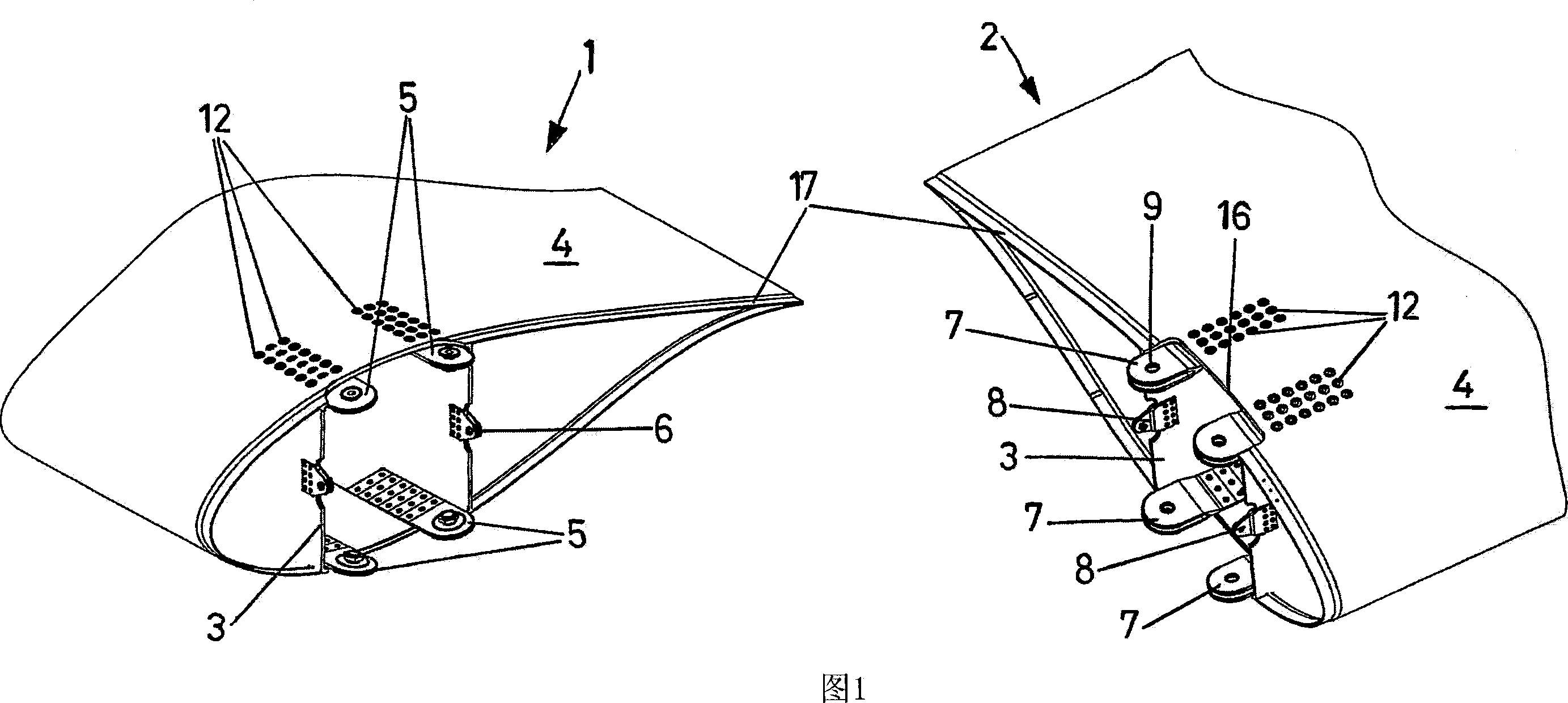
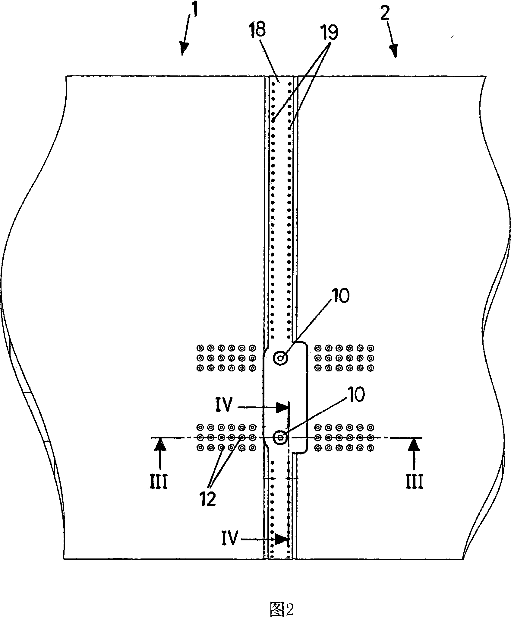
[0034] Figure 1 shows a perspective view of the faceable end segments of two consecutive modules 1 and 2 of a wind turbine blade. These blades consist essentially of internal stiffening structural members and an aerodynamic shell or box 4 attached to a beam 3, either of which may be constructed of a fiber reinforced resin of a different nature, in the described embodiment, the Internal reinforcement structural members take the form of structural beam...


PUM


Abstract

A wind turbine blade, which is transversely subdivided into two or more independent modules (1-2) constituted of external aerodynamic cases or walls (4) and an internal longitudinal reinforcement structure (3). The modules are provided with connecting means located in coincidence with the end sections of the longitudinal reinforcement structure (3) and are constituted of lugs (5-7, 6-8), projecting in coinciding portions provided with faceable holes (9) for receiving jointing elements.

Description

technical field [0001] The invention relates to a wind turbine blade which is subdivided transversely into two or more separate spans, wherein said spans are provided with connecting means at their end segments which may be opposite. Background technique [0002] Wind turbines are designed for ever increasing power. The components that interfere with the power of the wind turbine are the blades that form the rotor. The aerodynamic characteristics and size of the blades are essential elements for increasing the power of a wind turbine. For this reason, ever-growing blades are manufactured. [0003] Since wind turbines are often assembled in hard-to-reach places, the transportation of the blades is often a problem, mainly because of their length. [0004] In order to solve the problems that arise, the technique of subdividing the blade transversely into two or more separate sections or modules is known, said sections or modules being provided with couplings at their facing ...

Claims


Application Information

Patent Timeline
Patent Type & Authority Applications(China)
IPC IPC(8): F03D1/06
CPCF05B2240/302Y02E10/721F03D1/0675Y02E10/72
Inventor 何塞·伊格纳西奥·略伦特·冈萨雷斯塞尔希奥·贝莱斯·奥里亚
Owner GAMESA INNOVATION & TECH SA
Learn More