
Hand saw

A hand saw and handle technology, applied in pad saws, cross-cut saws, sawing equipment, etc., can solve the problems of difficulty in changing saw blades, instability, etc., and achieve convenient and replaceable saw blades, convenient replacement, and convenient fixed depth cutting Effect

Inactive Publication Date: 2007-04-18
KRAFTOOL MFG SHANGHAI
View PDF0 Cites 3 Cited by
  • Summary
  • Abstract
  • Description
  • Claims
  • Application Information

AI Technical Summary

Problems solved by technology

[0002] The current hand panel saw includes a saw blade, a handle, the saw blade has at least one flange, and one side of the handle is slotted, and they correspond to each other to achieve positioning. This method is based on the hand panel saw of German Patent No2931426, cl.B27B21 / 04, 1982 For example, its disadvantages are instability when cutting with a fixed depth of cut and difficulty in changing the saw blade

Method used


Image

  • Hand saw
  • Hand saw
  • Hand saw

Examples


Embodiment

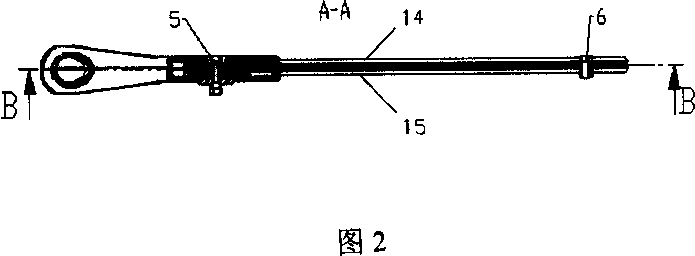
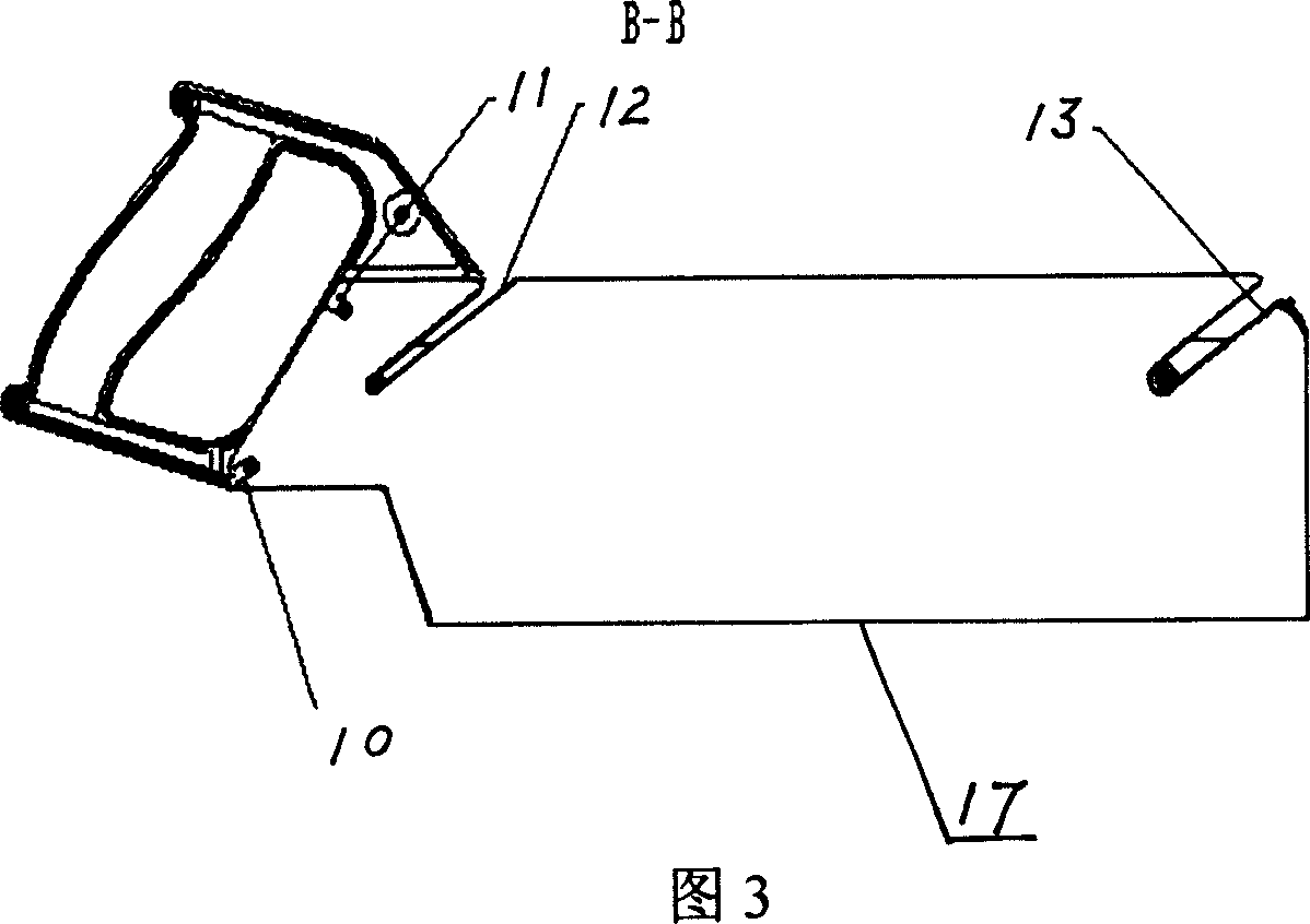
[0015] As shown in Figures 1, 2 and 3, they are schematic diagrams of the structure of the hand saw. The hand saw is composed of a replaceable blade 1, a handle 2, a limiter 3 and a wing nut 4.

[0016] The side of the replaceable blade 1 longitudinally close to the handle 2 is provided with a second groove 10 and a third groove 11 for positioning the third claw 7 and the fourth claw 8, and the lateral side of the replaceable blade 1 is provided with a positioning first card. The claw 5 and the fourth groove 12 and the fifth groove 13 for positioning the second claw 6 are provided with a blade 17 on the other side, and the fourth groove 12 overlaps with the first groove 9 of the handle 2 .

[0017] The handle 2 is provided with a first groove 9 on the side close to the third claw 7 and the fourth claw 8, overlapping with the fourth groove 12 of the replaceable blade 1 .

[0018] The limiter 3 is made up of two strip plates 14, 15, the limiter 3 is fixed on the handle 2 by the ...


PUM


Abstract

A hand saw has a handle, and features that its position limiter is fixed to handle via the shielded the first and the second fastening jaws, and an exchangeable saw blade in the position limiter is fixed to handle via the third and the fourth fastening jaws.

Description

technical field [0001] The invention relates to a hand saw, which can be used for sawing wood or other objects, and belongs to the technical field of tools. Background technique [0002] The current hand panel saw includes a saw blade, a handle, the saw blade has at least one flange, and one side of the handle is slotted, and they correspond to each other to achieve positioning. This method is based on the hand panel saw of German Patent No2931426, cl.B27B21 / 04, 1982 For example, its disadvantages are instability when cutting with a fixed depth of cut and difficulty in changing saw blades. Contents of the invention [0003] The purpose of the present invention is to invent a hand saw that can conveniently perform fixed depth cutting and replaceable saw blade. [0004] In order to achieve the above object, the technical solution of the present invention is to provide a hand panel saw, including a handle, characterized in that the limiter is fixed on the handle through the ...

Claims


Application Information

Patent Timeline
Patent Type & Authority Applications(China)
IPC IPC(8): B27B21/00B27B21/04B27B21/06
CPCB27B21/04B27B21/08
Inventor 温昊
Owner KRAFTOOL MFG SHANGHAI
Learn More