
A device and method for forming microstructures

A technology of microstructure and guiding device, applied in the direction of driving device, feeding device, large fixed member, etc., can solve the problems of insufficient cutting speed and correct surface quality, so as to reduce cutting power noise, avoid vibration, and reduce possible impact. Effect

Inactive Publication Date: 2007-04-11
SCHOTT AG
View PDF3 Cites 9 Cited by
  • Summary
  • Abstract
  • Description
  • Claims
  • Application Information

AI Technical Summary

Problems solved by technology

However, the cutting speeds thus achievable are not sufficient for correct machining of the aforementioned materials with sufficient surface quality, especially when rotationally asymmetric surface structures of the aforementioned type are to be formed

Method used


Image

  • A device and method for forming microstructures
  • A device and method for forming microstructures
  • A device and method for forming microstructures

Examples


Embodiment Construction

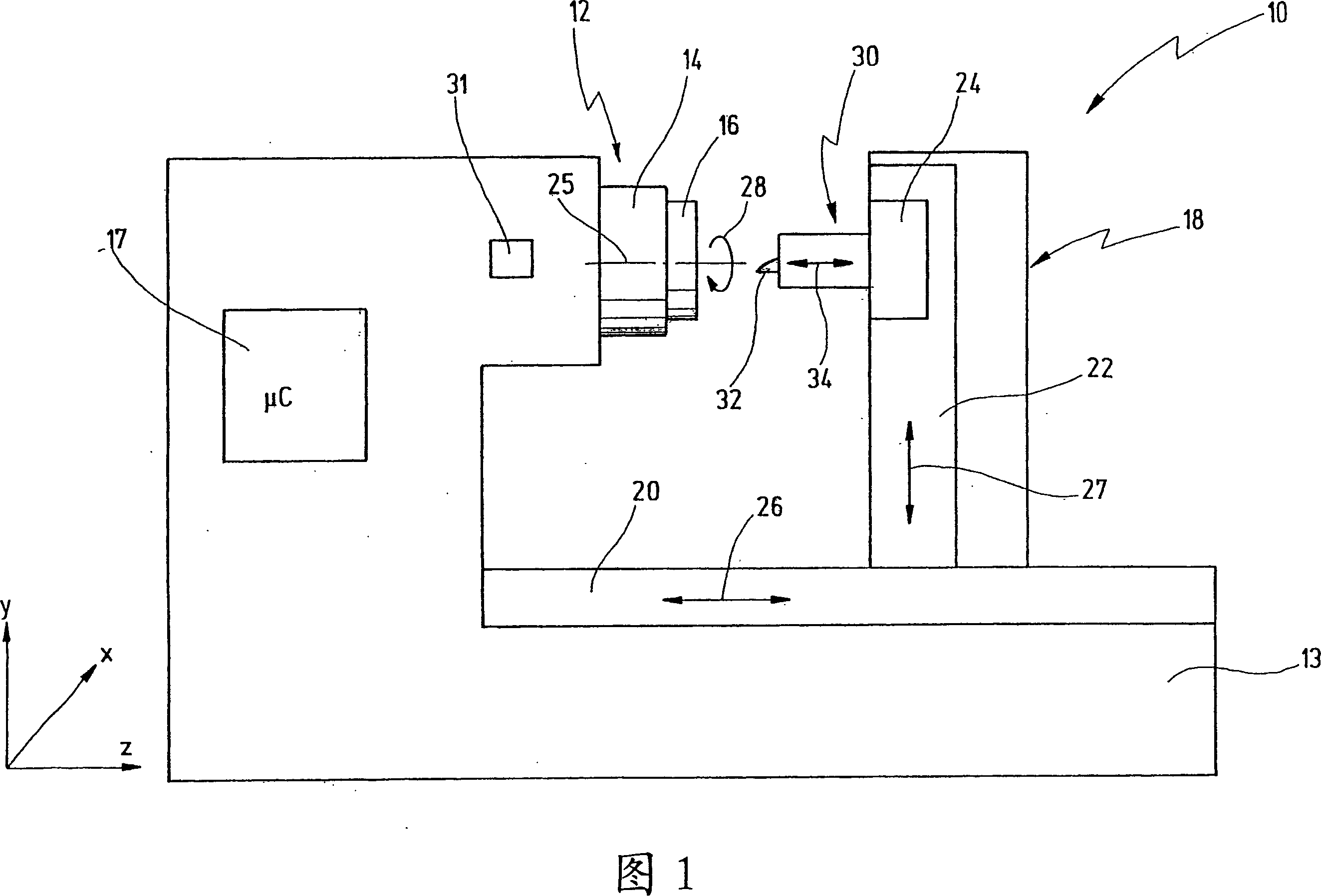
[0090] In FIG. 1 , a device according to the invention is shown very diagrammatically, indicated in its entirety by the reference numeral 10 .

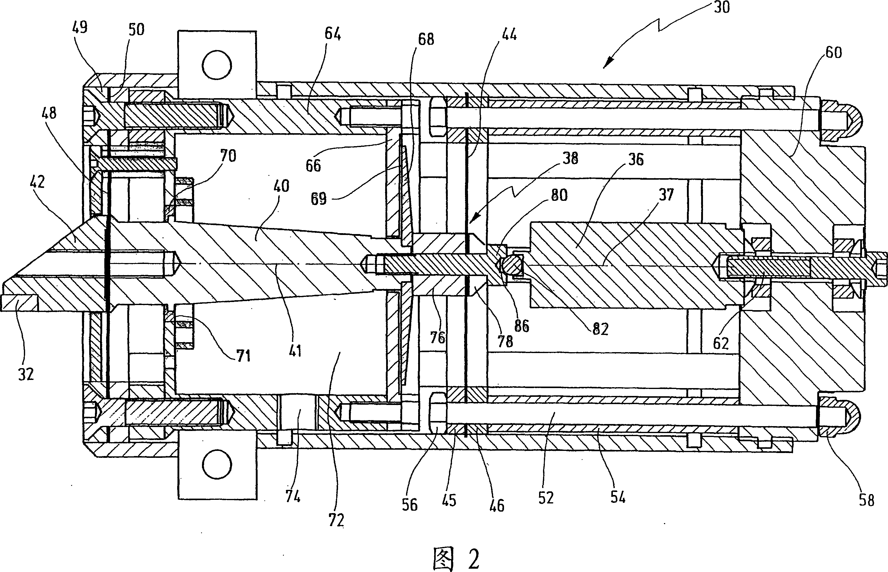
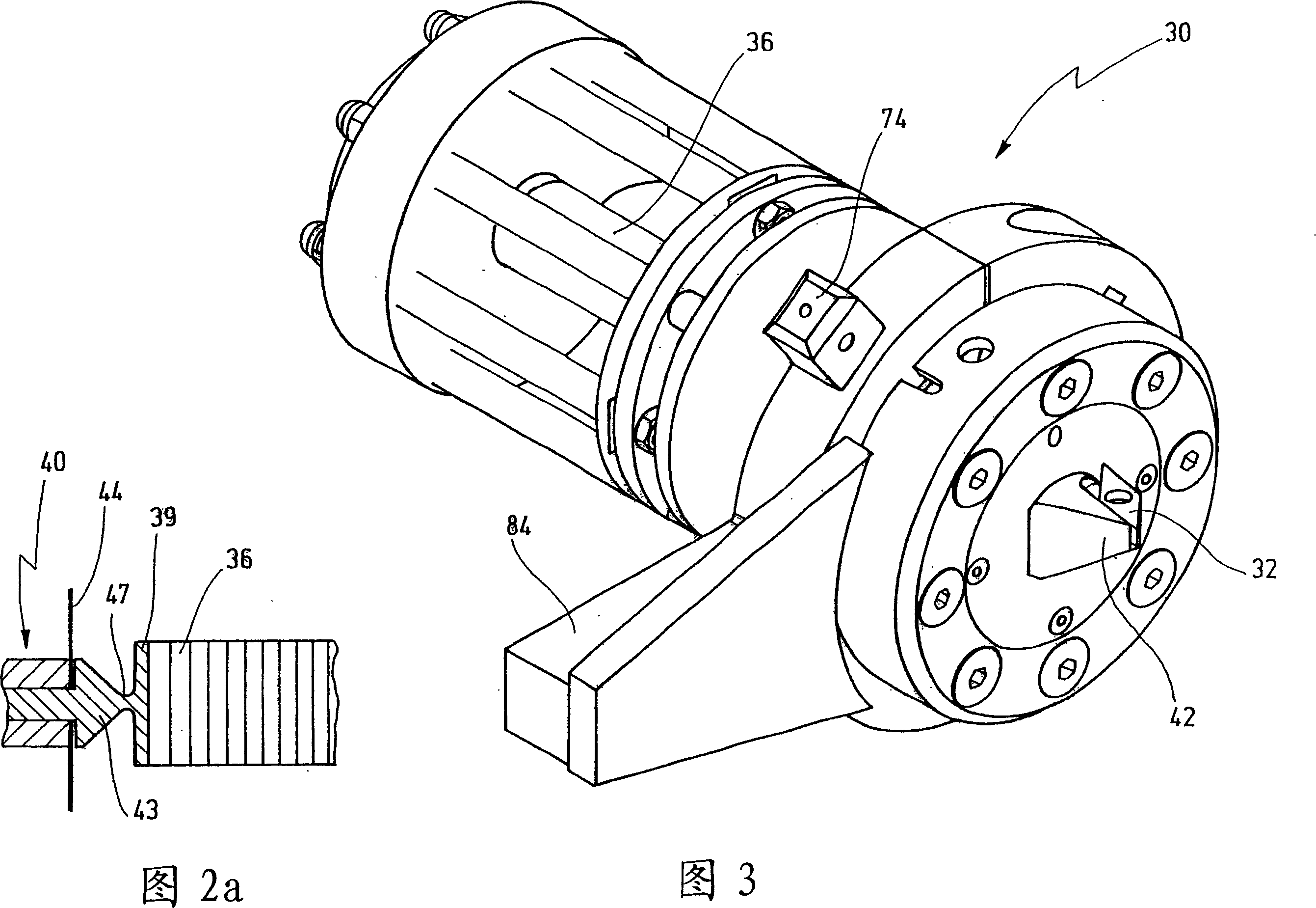
[0091] The device 10 according to the invention is a lathe which is additionally equipped with an actuator 30 for fast piezo-controlled movements of the tool 32 relative to the workpiece 16 . The device 10 includes a main shaft 12 which can be driven to rotate about its main shaft axis 25 as indicated by arrow 28 . Mounted on the spindle 12 is a gripper 14 in the form of a chuck adapted to grip a workpiece 16 . Along a guide extending in the z-direction (parallel to the spindle axis 25 ), a drive 20 is provided on the bed 13 of the device 10 , by means of which the tool carrier 18 can be moved in the z-direction, as indicated by the double arrow 26 . The tool carrier 18 is provided with a drive 22 by means of which the tool carrier 24 can be moved in the vertical direction (y-direction), as indicated by the double arrow 27 . The too...


PUM


Abstract

The invention relates to a device and a method for the production of microstructures, comprising: a spindle driven in rotation about a spindle axis, on which a housing for clamping a workpiece is provided; and an actuator (30), which has a rapid drive (36), in particular a piezo-drive for generation of a rapid movement of a tool (32) in a direction essentially perpendicular to the workpiece surface, thereby the actuator (30) may be positioned by means of a further drive (24) for generation of a linear movement in a first direction along a workpiece surface for machining (24). The rapid drive (36) is coupled to the tool (32) by means of a guide device (38) which permits an adjustment of the tool (32) in the axial direction of the rapid drive (36) against a return force and which presents a high rigidity in a plane perpendicular thereto. The applied control technology permits a precise and reproducible production of microstructures using the dynamic system properties.

Description

technical field [0001] The invention relates to a device for forming microstructures by means of a spindle adapted to be driven in rotation about its longitudinal axis and provided with a clamp for clamping a workpiece, the device having an actuator provided with a fast drive, The fast drive is adapted to rapidly move the tool in a direction generally perpendicular to the surface of the workpiece, the actuator being positionable along the surface of the workpiece for operation with an additional drive adapted to produce a linear feed motion in a first direction. [0002] The invention also relates to an actuator suitable for such a device. [0003] Finally, the invention relates to a method for forming a microstructured surface on a workpiece rotatable by a spindle using a tool which can be driven by an actuator and which can be positioned along the workpiece by means of the drive in a linear direction, It is also movable towards the surface of the workpiece by the actuator i...

Claims


Application Information

Patent Timeline
Patent Type & Authority Applications(China)
IPC IPC(8): B23Q1/58B23Q1/34B23Q5/027B23Q5/32
CPCB23Q1/34B23Q5/32
Inventor 海因里希·奥斯藤达普
Owner SCHOTT AG
Learn More