
Filter glass for cutting fore infrared rays

A filter glass and near-infrared technology, applied in the field of near-infrared cut-off filter glass, can solve the problems of difficulty in disappearing stripes, insufficient weather resistance improvement, large thermal expansion coefficient, etc., and achieves good weather resistance and near infrared cutoff. Excellent properties and small thermal expansion coefficient

Inactive Publication Date: 2011-07-06
NIHON YAMAMURA GLASS CO LTD
View PDF3 Cites 0 Cited by
  • Summary
  • Abstract
  • Description
  • Claims
  • Application Information

AI Technical Summary

Problems solved by technology

[0006] However, in the glasses disclosed in the above-mentioned Patent Documents 1 and 2, P 2 o 5 Content of 45% by weight or less, there is a problem that the formability of glass is not good
In addition, due to the high coefficient of thermal expansion, there is a problem that it is easy to break when making a glass block.
[0007] In addition, the glass disclosed in the above-mentioned Patent Document 3, although P 2 o 5 The content is 46% by weight or more, but the problem of insufficient improvement of weather resistance remains
[0008] In addition, in the conventional fluorophosphate-based glass, the viscosity of the glass is low, and there is a problem that streaks are difficult to disappear.

Method used


Image

  • Filter glass for cutting fore infrared rays

Examples


Embodiment 1

[0070] As shown in Table 1, according to the glass composition relative to 100% by weight of P 2 o 5 : 46.0% by weight, Al 2 o 3 : 9.0% by weight, ZnF 2 : 5.0% by weight, BaF 2 : 18.7% by weight, CaF 2 : 1.1% by weight, SrF 2 : 6.8% by weight, NaF: 2.0% by weight, LiF: 9.4% by weight, Y 2 o 3 : Base glass composed of 2.0% by weight, containing CuO: 6.0% by weight, each component raw material was blended.

[0071] Thereafter, the prepared raw materials were melted in a platinum crucible placed in an electric furnace set at 900° C. for 1 hour, and flowed out into a preheated iron plate mold to produce a glass gob. Then, the produced glass block was placed in an electric furnace set at a temperature approximately 50°C higher than the expected glass transition point, and after slow cooling, it was cut and ground to prepare a sample for measuring the thermal expansion coefficient and softening point.

[0072] The results are shown in Table 1, the coefficient of thermal exp...

Embodiment 2~27

[0082] The raw materials of the same components as those in Example 1 were prepared so as to obtain the compositions shown in Tables 1 to 4, glass flakes were produced, and after slow cooling, they were cut out and ground to prepare samples for measuring thermal expansion coefficient and softening point.

[0083] The results are shown in Tables 1-4.

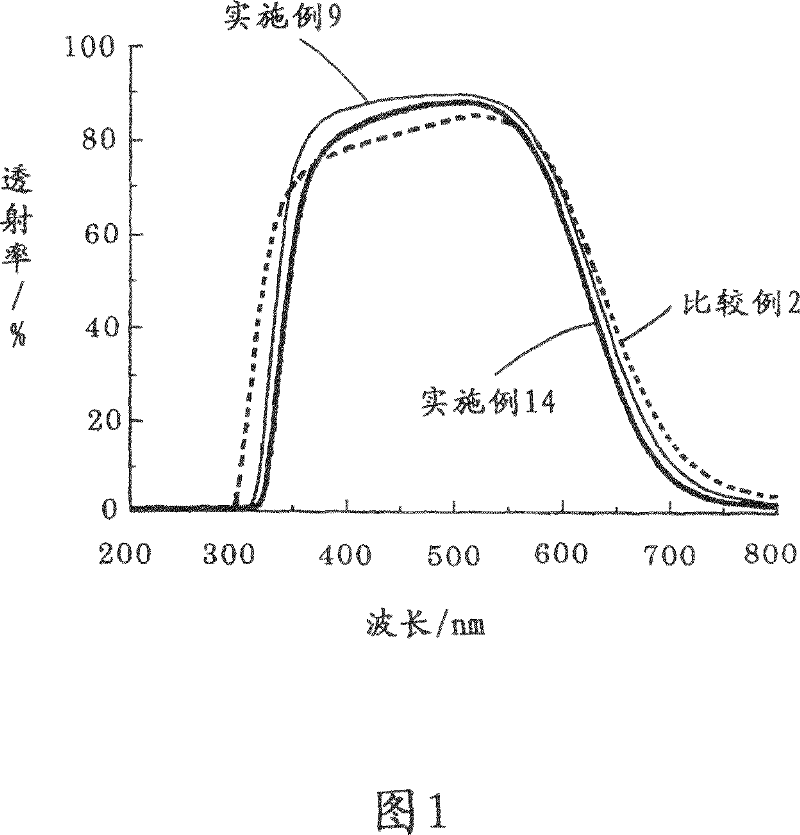
[0084] figure 1 The spectral transmittances of Examples 9, 14, and Comparative Example 2 are shown.

[0085] As evident from Examples 1 to 27 and Comparative Examples 1 and 2 above, it can be seen that the glass of the Examples of the present invention has better weather resistance than the Comparative Examples and is less likely to be cracked due to its small coefficient of thermal expansion. Also in figure 1 From the spectral transmittance curve shown, it can be seen that the glass of the example of the present invention has a higher transmittance at a wavelength of 350 to 600 nm than that of a comparative example, and on the...


PUM

PropertyMeasurementUnit
glass transition temperatureaaaaaaaaaa

Abstract

The object of the present invention is to provide filter glass for cutting near-infrared rays, which is excellent in near-infrared ray cutting properties, has good weatherability and a small coefficient of thermal expansion, and is thereby hardly cracked during manufacturing of a block, and in which striae disappear easily. The filter glass for cutting near-infrared rays comprises, by weight expressed in terms of oxide and fluoride, 46-60% P2O5, 5-11% Al2O3, 1-10% of at least one kind of ZnF2, MnF2, and InF3, 10-45% of at least one kind of CaF2, SrF2, and BaF2, 0.1-15% LiF, 0.1-15% NaF, and 0.4-3% of at least one kind of SiO2, ZrO2, La2O3, Y2O3, and Yb2O3, wherein CuO is contained in an amount of 0.5-8% to 100% of base glass components containing 5-20% F and 25-40% O.

Description

technical field [0001] The present invention relates to a filter glass composition for cutting near infrared rays. More specifically, it relates to a filter glass for cutting near-infrared rays that is excellent in sharp cutting characteristics in the vicinity of 600 to 800 nm, which can be used as a filter glass for color compensation of digital cameras and the like. Background technique [0002] Recently, glass obtained by adding CuO to phosphate-based glass can be used as filter glass for cutting near infrared rays. However, in recent years, since the weather resistance of phosphate-based glass is poor, in order to improve it, glass in which CuO is added to fluorophosphate-based glass in which fluorine is introduced into phosphate-based glass has been proposed (Patent Documents 1, 2, 3 ). [0003] [Patent Document 1] Japanese Patent Publication No. 6-43254 [0004] [Patent Document 2] Japanese Patent Publication No. 7-80689 [0005] [Patent Document 3] Japanese Patent...

Claims


Application Information

Patent Timeline
Patent Type & Authority Patents(China)
IPC IPC(8): C03C4/08C03C3/062
CPCC03C4/082C03C3/247C03C3/062C03C3/12C03C3/16C03C3/17C03C4/08
Inventor 前田浩三更冈真衣子
Owner NIHON YAMAMURA GLASS CO LTD
Learn More