
Gas spring

A gas spring and volume technology, applied in the field of gas springs, can solve the problem of no effective volume expansion, and achieve the effect of preventing vibration and lateral displacement

Inactive Publication Date: 2007-02-28
STABILUS
View PDF2 Cites 5 Cited by
  • Summary
  • Abstract
  • Description
  • Claims
  • Application Information

AI Technical Summary

Problems solved by technology

[0004] However, practice has proved that none of these compensating media is satisfactory in all respects
In particular, conventionally used mineral oils do not have a satisfactory effective volume expansion in the range of operating conditions of gas springs, which are generally at temperatures of about -30° C. on the one hand and pressures of about 50 bar To the other hand between a temperature of about +80°C and a pressure of about 440 bar

Method used


Image

  • Gas spring
  • Gas spring
  • Gas spring

Examples


Embodiment Construction

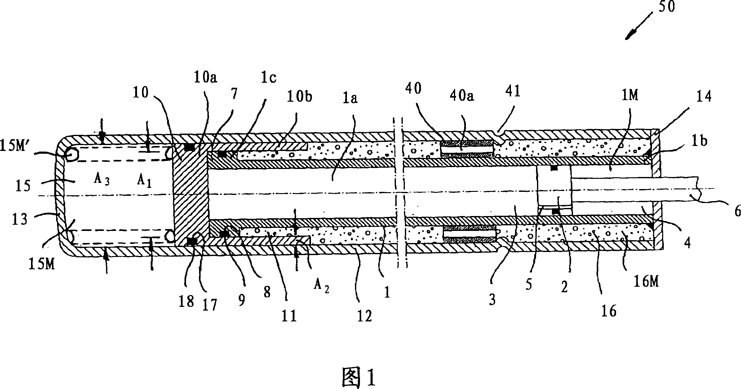
[0045] In FIG. 1 , a gas spring according to the invention is indicated generally at 50 . The gas spring 50 has a working cylinder 1 in which a working piston 2 is displaceably guided. The working piston 2 divides the interior 1 a of the working cylinder 1 into a first working chamber 3 and a second working chamber 4 . The piston rod 6 is fastened to the working piston 2 , passes through the second working chamber 4 , which is closed from the environment, and is guided in a sealed manner outside the gas spring 1 .

[0046] It is thus possible to attenuate the movement of the working piston 2 in the inner chamber 1a of the working cylinder 1, which is filled with compressed gas 1M, the orifice 5 connecting the first working chamber 3 with the second working chamber 4 is provided In working piston 2. However, in addition to or as an alternative to the orifice 5 , at least one longitudinal groove can also be formed in the cylinder 1 .

[0047] The open end 1 c of the working c...


PUM


Abstract

The invention relates to a gas spring which uses a compensating medium acting on a compensating piston in order to compensate the dependence on temperature of its characteristic. According to a first aspect of the invention, a compensating medium ( 16 M) is selected whereof the critical temperature (TK) is between the lower limit temperature (Tlower) and a temperature exceeding the upper limit temperature (Tupper) of the range of operating temperatures of the gas spring ( 50 ) by up to 100 DEG C, and the gas spring ( 50 ) is designed such that, at an operating temperature (TB) of the gas spring ( 50 ) not exceeding the critical temperature (TK) of the compensating medium ( 16 M), the point indicating the state of the compensating medium ( 16 M) lies on or above the vapor pressure curve. According to a second aspect, in order to simplify the structure of the gas spring ( 50 ), a single compensating piston ( 10 ) which takes the shape of a cup is used and separates the working chamber ( 1 a), the compensating chamber ( 16 ) and the restoring chamber ( 15 ) of the gas spring ( 50 ) from one another.

Description

technical field [0001] The invention relates to a gas spring with a working cylinder which, together with a compensating piston arrangement, delimits a working chamber filled with a working medium, and a working rod which protrudes movably through a hole in the working cylinder. Inside the working chamber, where the compensating piston device is driven by the pressure of the working medium and the pressure of the compensating medium and the restoring medium, which is arranged in the compensating chamber and expands when the temperature rises, so that the volume of the working chamber Increase, the reset medium is arranged in the reset chamber, so that the volume of the working chamber is reduced. Background technique [0002] Gas springs of this type are known in the prior art, the purpose of which is to compensate for the temperature dependence of such gas springs, which are characterized by the use of a compensation medium. As an example, the reader is referred to DE31412...

Claims


Application Information

Patent Timeline
Patent Type & Authority Applications(China)
IPC IPC(8): F16F9/02
Inventor H·安泽尔M·布勒德S·邦内克泽尔S·恩德斯A·克尔R·马斯曼R·明特根M·纳德勒W·尼拉奇克尔R·绍尔
Owner STABILUS
Learn More