
Electrovacuum tube with dual anodes, and assembling method

A technology of electric vacuum tube and double anode, which is applied in the direction of vacuum tube, discharge tube, non-electron emitting anode, etc., and can solve the problems of increased anode spacing and concentricity error

Inactive Publication Date: 2007-02-21
INST OF ELECTRONICS CHINESE ACAD OF SCI
View PDF0 Cites 3 Cited by
  • Summary
  • Abstract
  • Description
  • Claims
  • Application Information

AI Technical Summary

Problems solved by technology

In this known structure, the positioning of the two anodes includes the distance between the two anodes and the concentricity of the two anodes. The existing positioning method relies on the precise processing of each part to ensure the distance and concentricity between the two anodes. Due to the cumulative error of each part, the spacing and concentric error between the anodes will increase

Method used

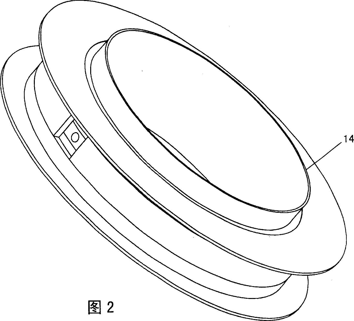
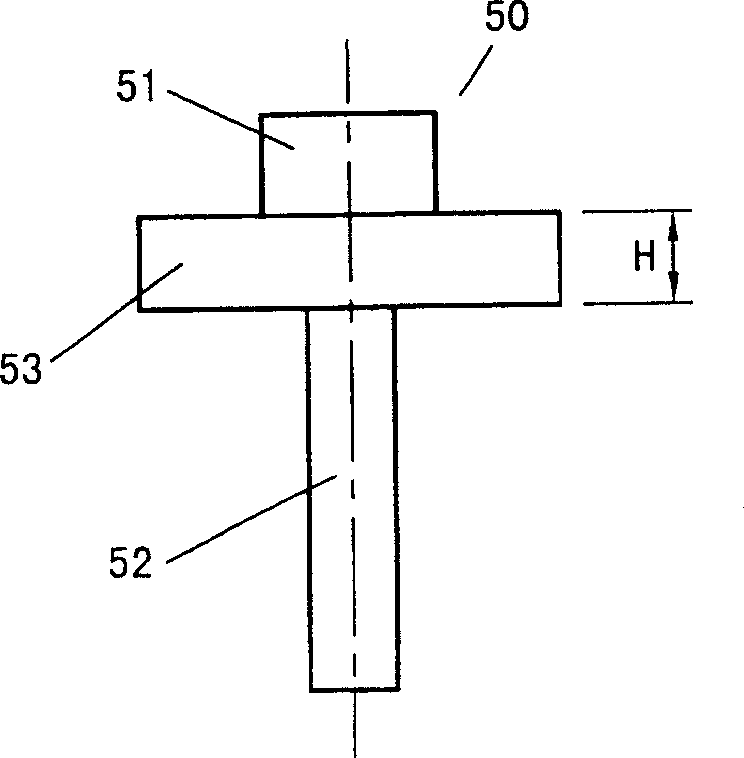

Image

  • Electrovacuum tube with dual anodes, and assembling method
  • Electrovacuum tube with dual anodes, and assembling method
  • Electrovacuum tube with dual anodes, and assembling method

Examples


Embodiment Construction

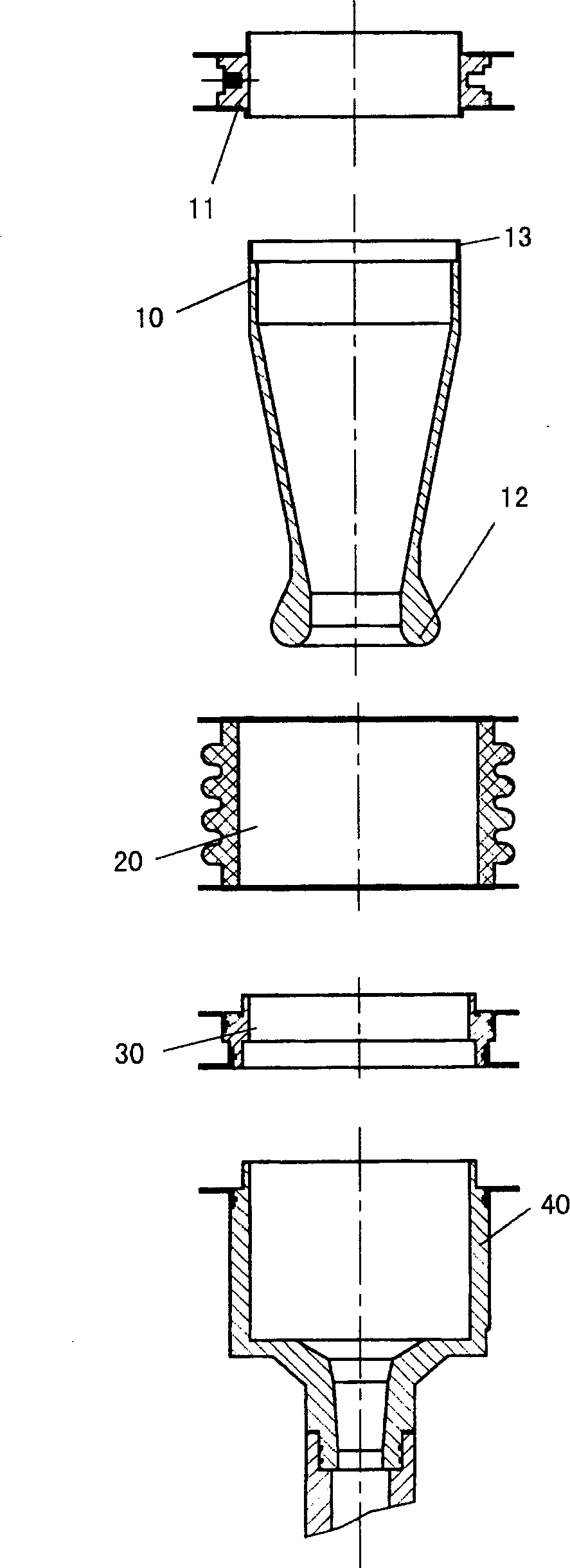
[0016] see figure 1 , the structure of the double-anode electric vacuum tube provided by the present invention includes in order: the first anode 10, the first anode seat 11, the ceramic insulating section assembly 20, the transition section assembly 30 and the second anode 40, the transition section assembly 30 and the first anode An anode 10 is made of oxygen-free copper like the second anode 40 , and the inner diameter of the transition section assembly 30 is the same as the inner diameter of the second anode 40 . In order to ensure accurate positioning and connection stability between the transition section assembly 30, the ceramic insulating section assembly 20 and the second anode assembly 40, a step 31 is provided outside one port of the transition section assembly 30, and a step 31 is provided on the inside of the other port. A step 32 is provided, wherein the outer step 31 is connected with the inner diameter of a port of the ceramic insulating component 20 , and the ...


PUM


Abstract

First anode is connected to one end of ceramic insulation sect module. The other end of the ceramic insulation sect module is connected to a terminal port of a transition sect module, which is connected to second anode. First anode seat is installed on the first anode, and a featheredge area as a soldering edge is setup at tail part of the first anode. There is a lamellar soldering edge between same terminal ports of first anode seat and the tail part of the first anode. Assembling procedure includes steps: inserting die in to second anode; placing the transition sect module, the ceramic insulation sect module, first anode, and first anode seat; inner diameter of first anode head sheathed on up end of the die; being placed to first anode, tool bar impresses force downward; then, soldering two modules, first anode, and first anode seat as integrated module; taking die out and replacing second anode back to original position; soldering second anode and transition sect module.

Description

technical field [0001] The invention relates to a structure of an electric vacuum tube, in particular to a structure of a double-anode electric vacuum tube. [0002] The invention also relates to a method of assembling the above structure. Background technique [0003] The structure of the known electric vacuum double anode is that a ceramic insulating section assembly is arranged between the first anode assembly and the second anode assembly. In this known structure, the positioning of the two anodes includes the distance between the two anodes and the concentricity of the two anodes. The existing positioning method relies on the precise processing of each part to ensure the distance and concentricity between the two anodes. However, due to the cumulative error of each part, the spacing and concentric error between the anodes will increase. Contents of the invention [0004] The purpose of the present invention is to provide a structure of a double-anode electric vacuum...

Claims


Application Information

Patent Timeline
IPC IPC(8): H01J19/32H01J21/00H01J9/00
Inventor 顾伟张世昌刘濮鲲
Owner INST OF ELECTRONICS CHINESE ACAD OF SCI
Learn More