
Booster-type compressor

A technology for compressors and compressed gases, which is applied in the direction of liquid variable displacement machinery, mechanical equipment, machines/engines, etc., and can solve problems such as temperature rise and damage

Inactive Publication Date: 2007-02-21
ANEST IWATA CORP
View PDF0 Cites 4 Cited by
  • Summary
  • Abstract
  • Description
  • Claims
  • Application Information

AI Technical Summary

Problems solved by technology

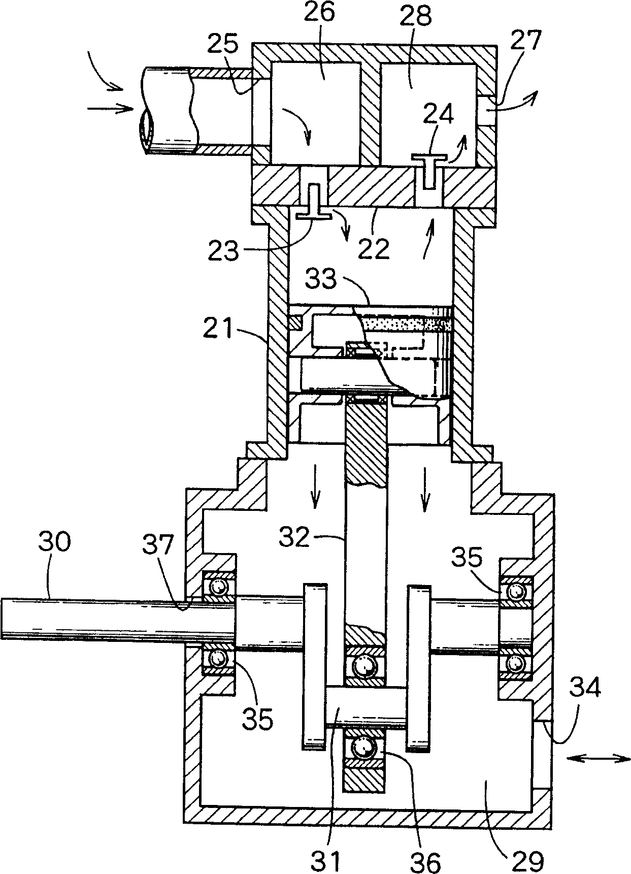
[0006] In order to overcome the above-mentioned problems in the supercharged compressor, the air holes 34 of the crankcase 29 should be closed, however, the temperature in the sealed crankcase 29 will rise during operation, so that the bearings for the drive shaft 30 and the crankshaft 31 will be damaged. 35, 36 and seals 37

Method used


Image

  • Booster-type compressor
  • Booster-type compressor

Examples


Embodiment Construction

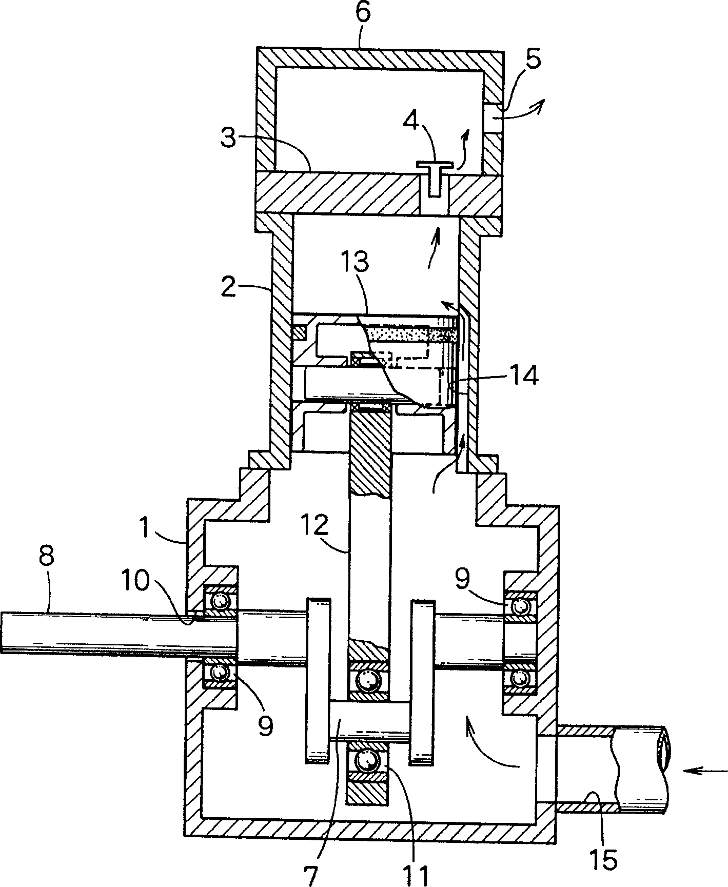
[0011] Below, will refer to figure 1 , the booster compressor of the present invention will be described.

[0012] In the upper part of the crankcase 1, a discharge check valve 4 is provided in the top wall 3 of the cylinder 2, and above the top wall 3, a discharge chamber 6 with a discharge hole 5 is provided.

[0013] In the crankcase 1, a drive shaft 8 is rotatably mounted via bearings 9, 9 and seals 10, which is integrally connected with the crankshaft 7 and driven by a suitable power source. The piston rod 12 is rotatably connected to the crankshaft 7 via a bearing 11 at one end, and is rotatably connected to the piston 13 in the cylinder 2 at the other end.

[0014] A gas guide groove 14 is formed on the inner periphery of the cylinder 2 . When the piston 13 is at the lowest position, the lower end of the gas guiding groove 14 communicates with the inside of the crankcase 1 , and the upper end of the gas guiding groove 14 communicates with the space above the piston 1...


PUM


Abstract

A compressed gas is introduced into a casing. A piston pivotally connected to a reciprocating mechanism moves up and down in a cylinder. The compressed gas in the casing is sent to a space on the piston through a groove formed in the inner circumference of the cylinder and is further compressed in the space by the piston.

Description

technical field [0001] The invention relates to a booster compressor which uses a reciprocating piston to compress compressed gas. Background technique [0002] exist figure 2 shows a conventional booster compressor in which a suction check valve 23 is formed on one side of a top wall 22 of a cylinder 21 and a discharge check valve 24 is formed on the other side of the top wall 22 . A suction chamber 26 having an inlet 25 and a discharge chamber 28 having an outlet 27 are formed above the suction check valve 23 and the discharge check valve 24, respectively. A crankshaft 31 is arranged in the crankcase 29 below the cylinder 21, and the crankshaft is connected as a whole with a drive shaft 30 driven by an external power source. A piston 33 in the cylinder 21 is reciprocated by a crankshaft 31 by a piston rod 32 . Via the suction check valve 23, the N 2 Such compressed gas is introduced into the space above the piston 33 , compressed, and then discharged via the discharge ...

Claims


Application Information

Patent Timeline
Patent Type & Authority Applications(China)
IPC IPC(8): F04B35/00F04B39/10
CPCF04B7/04F04B39/122
Inventor 井上弘
Owner ANEST IWATA CORP
Learn More