Electronic device and radio communication terminal
An electronic device and wireless communication technology, applied in the direction of image communication, television, electrical components, etc., can solve the problems of connection reliability reduction and cost increase, and achieve the effect of eliminating reliability problems, easy installation, and eliminating cost increase
- Summary
- Abstract
- Description
- Claims
- Application Information
AI Technical Summary
Problems solved by technology
Method used
Image


Examples
Embodiment 1
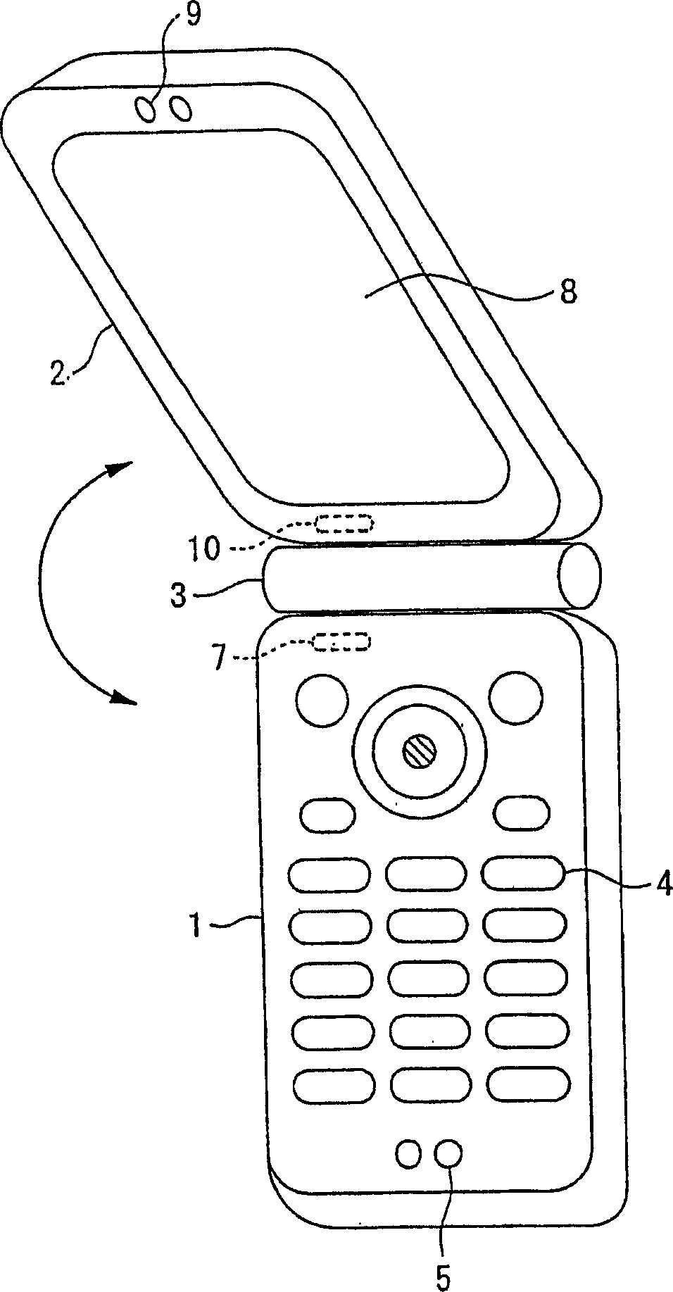
[0061] figure 1 It is a perspective view showing the state when the clamshell mobile phone to which the wireless communication control method of the present invention is applied is opened, figure 2 It is a perspective view showing the state when the clamshell mobile phone to which the wireless communication control method of the present invention is applied is closed.
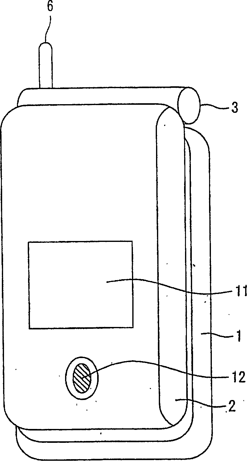
[0062] exist figure 1 and figure 2 Among them, the operation button 4 is arranged on the surface of the first case part 1 , the microphone 5 is provided at the lower end of the first case part 1 , and the external wireless communication antenna 6 is attached to the upper end of the first case part 1 . Furthermore, a display body 8 is provided on the surface of the second case part 2 , and a speaker 9 is provided on the upper end of the second case part 2 . A display body 11 and an imaging element 12 are provided on the back surface of the second housing portion 2 . In addition, as the display bodies 8 a...
Embodiment 2
[0069] image 3 It is a perspective view showing the appearance of a rotary mobile phone to which the wireless communication control method of the present invention is applied.
[0070] exist image 3 Among them, the operation button 24 is arranged on the surface of the first case part 21 , the microphone 25 is provided at the lower end of the first case part 21 , and the external wireless communication antenna 26 is attached to the upper end of the first case part 21 . Furthermore, a display body 28 is provided on the surface of the second case part 22 , and a speaker 29 is provided on the upper end of the second case part 22 . Internal wireless communication antennas 27 and 30 for performing internal wireless communication between the first case portion 21 and the second case portion 22 are respectively provided in the first case portion 21 and the second case portion 22 .
[0071] And, the first casing part 21 and the second casing part 22 are connected by the hinge 23, b...
Embodiment 3
[0076] Figure 4 It is a cross-sectional view showing the main part of the embodiment of another electronic device.
[0077] exist Figure 4 In FIG. 1 , the electronic device is divided into a main body 135 and a display 139 , which are integrally formed by a hinge 137 . The main body substrate 133 is in charge of the function control of the main body of the electronic device. Various input and output devices, such as a keyboard and a display device, are connected to the electronic device. 134 denotes a keyboard as an input device, and 136 denotes a liquid crystal display as a display device. 138 denotes a liquid crystal controller that generates display data under the control of the electronic circuit on the main body substrate 133 . Here, a transmitting antenna 141 and a receiving antenna 140 are provided in the electronic device for internal wireless communication between the main body portion 135 and the display portion 139 .
[0078] Furthermore, the display data gen...
PUM
 Abstract
Description
Claims
Application Information
 - R&D
- Intellectual Property
- Life Sciences
- Materials
- Tech Scout
- Unparalleled Data Quality
- Higher Quality Content
- 60% Fewer Hallucinations
Browse by: Latest US Patents, China's latest patents, Technical Efficacy Thesaurus, Application Domain, Technology Topic, Popular Technical Reports.
© 2025 PatSnap. All rights reserved.Legal|Privacy policy|Modern Slavery Act Transparency Statement|Sitemap|About US| Contact US: help@patsnap.com