
Speaker system

A speaker and speaker group technology, applied in the field of speaker systems, can solve problems such as low efficiency of speakers, achieve the effects of increasing volume, improving system efficiency, and improving sound quality

Inactive Publication Date: 2007-01-24
张壮发
View PDF0 Cites 3 Cited by
  • Summary
  • Abstract
  • Description
  • Claims
  • Application Information

AI Technical Summary

Problems solved by technology

However, the speakers commonly used in traditional speaker systems have low efficiency problems:
There is still room for improvement, such as the standing wave of the cabinet caused by the sound wave emitted from the back of the diaphragm reflected in the cabinet

Method used


Image

  • Speaker system
  • Speaker system
  • Speaker system

Examples


Embodiment Construction

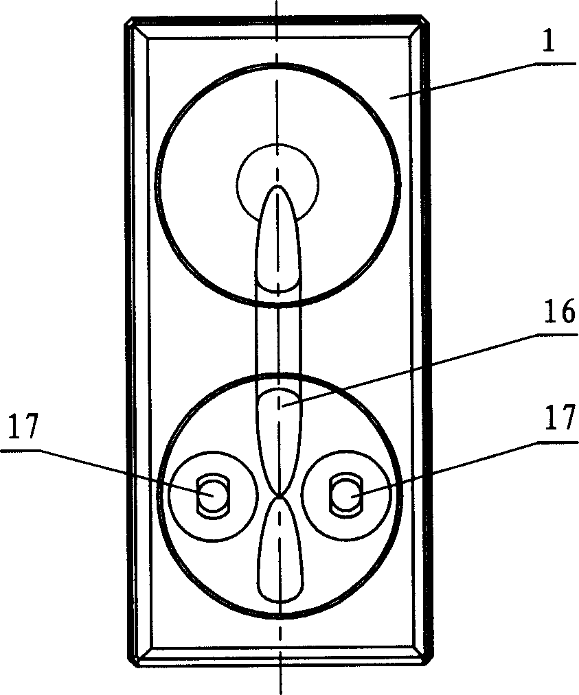
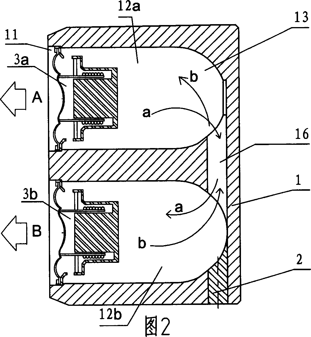
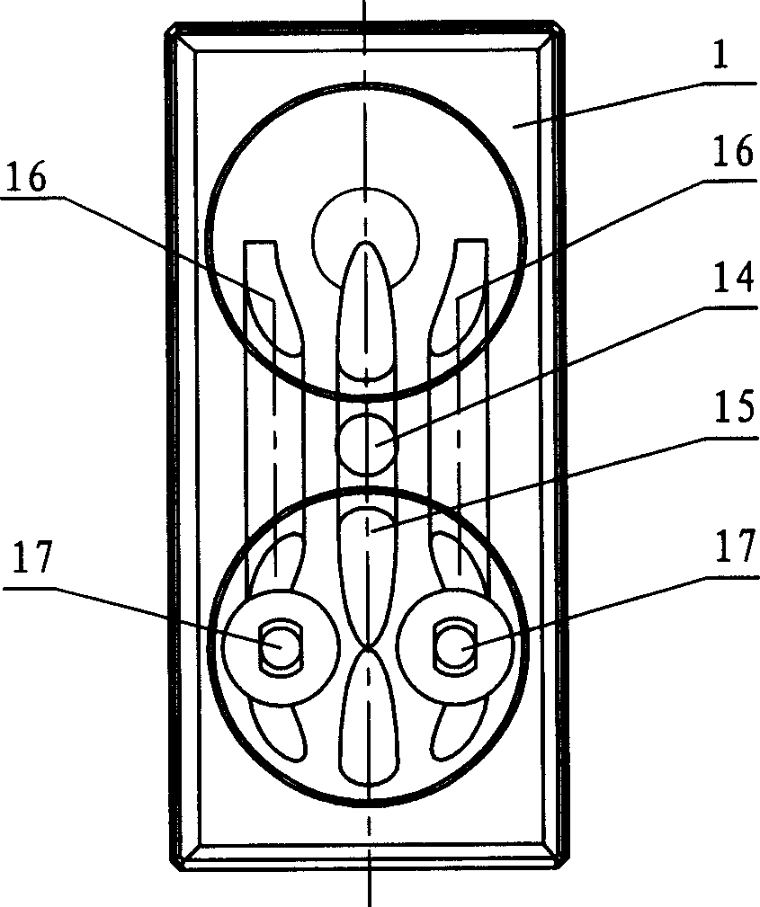
[0025] exist figure 1 2. In the speaker body 1 of the speaker system embodiment 1 of the present invention shown in FIG. 2, two speakers 3a and 3b with the same performance are installed, and the two speakers are connected according to the polarity. Each loudspeaker is installed in the opening end of the corresponding independent sound chamber 12 in the sound box body, and in the mounting hole 11 of the loudspeaker. The shape and size of the two sound chambers 12a and 12b are the same. The side walls of the sound chambers 12a, 12b are cylindrical in shape, and the rear part 13 of the sound chamber is hemispherical. The two sound chambers communicate with each other through the connecting pipe 16 . The connecting terminal of loudspeaker is installed by mounting hole 17, and the process hole of connecting pipe 16 is blocked with stopper 2.

[0026] exist image 3 , Figure 4 In the speaker system embodiment 2 of the present invention shown, the end face of the speaker body ...


PUM


Abstract

This invention discloses a loudspeaker system including a sound box, at least two loudspeaker sets in the same performance and composed of one or more than one loudspeakers, each set is installed in the open-end of an independent sound chamber in the box, the chambers are in same shape and size, the adjacent chambers are run-through by a connection tube, and the structure of this invention is favorable to realizing resonance of the loudspeaker sets.

Description

technical field [0001] The invention relates to the field of audio, in particular to a loudspeaker system. Background technique [0002] The audio system industry is constantly pursuing small size, high volume and high sound quality in the production of speaker systems. However, the speakers commonly used in traditional speaker systems have low efficiency problems: [0003] Closed speaker - the speaker is completely sealed, and the sound waves emitted from the back of the speaker diaphragm are isolated from the outside world. Although the sound wave interference from the front and rear of the diaphragm is eliminated, because the air in the box is completely isolated from the outside world, the air in the box will be broken when the speaker is working. Add damping to the speaker, so the box must be made larger to have a better low-frequency playback effect. [0004] Vented Speaker - Inverts a portion of the sound waves emitted from the back of the speaker pack's diaphragm b...

Claims


Application Information

Patent Timeline
IPC IPC(8): H04R1/20
Inventor 张壮发
Owner 张壮发
Learn More