Fitting for fixing a doorwing

A door leaf and hinge technology, applied in the field of fixing door leaf devices, can solve the problems of calcification, inconvenience of turning the door leaf, disturbing noise of the door leaf, etc.

Inactive Publication Date: 2007-01-24
FOREMOST INT
View PDF1 Cites 3 Cited by
  • Summary
  • Abstract
  • Description
  • Claims
  • Application Information

AI Technical Summary

Problems solved by technology

Moreover, relatively large forces are exerted on the cross bracing of the door leaf at different swing positions, so it is not very convenient to turn the door leaf
Furthermore, turning the door leaf with this...

Method used


Image

  • Fitting for fixing a doorwing
  • Fitting for fixing a doorwing
  • Fitting for fixing a doorwing

Examples


Embodiment Construction

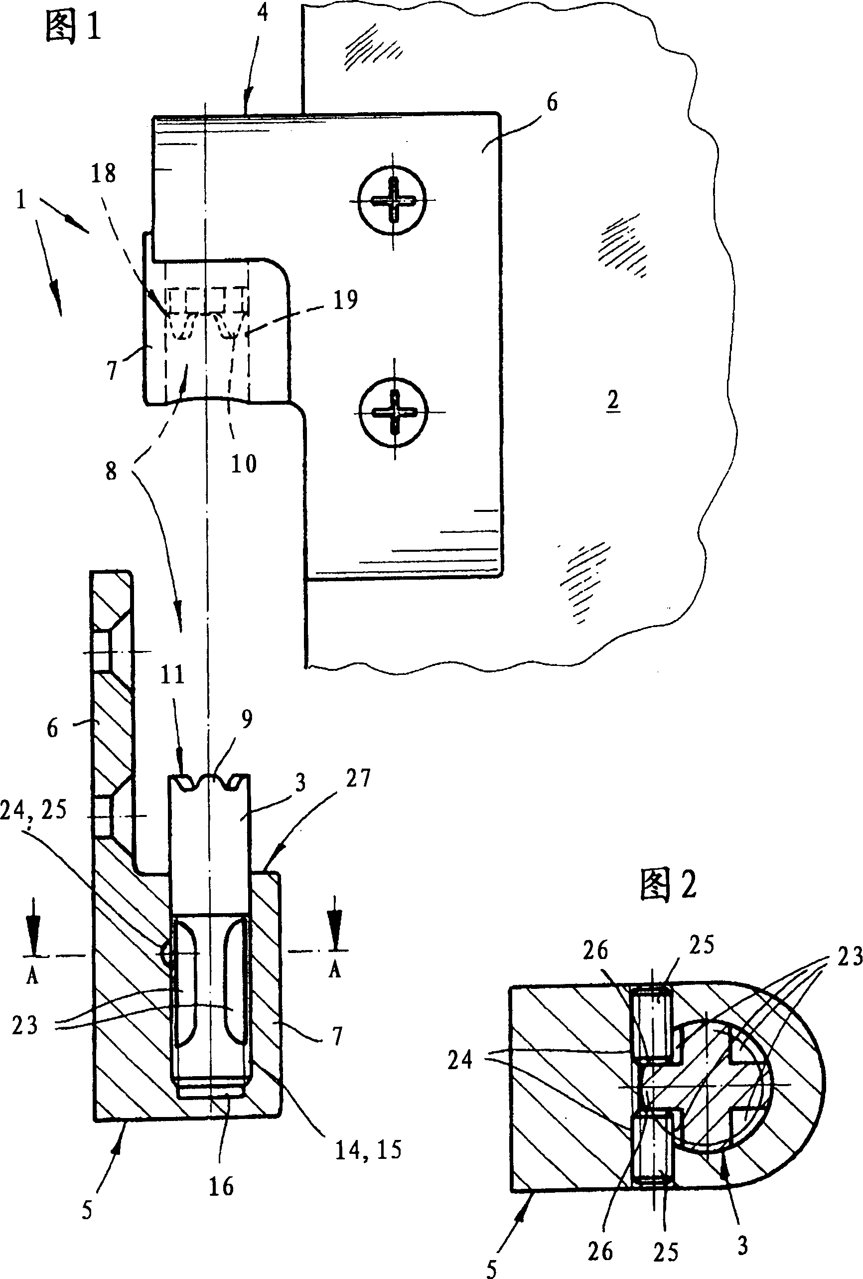
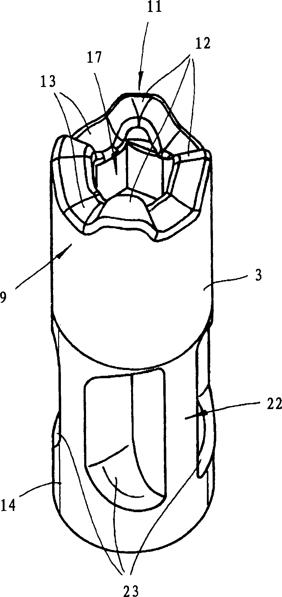
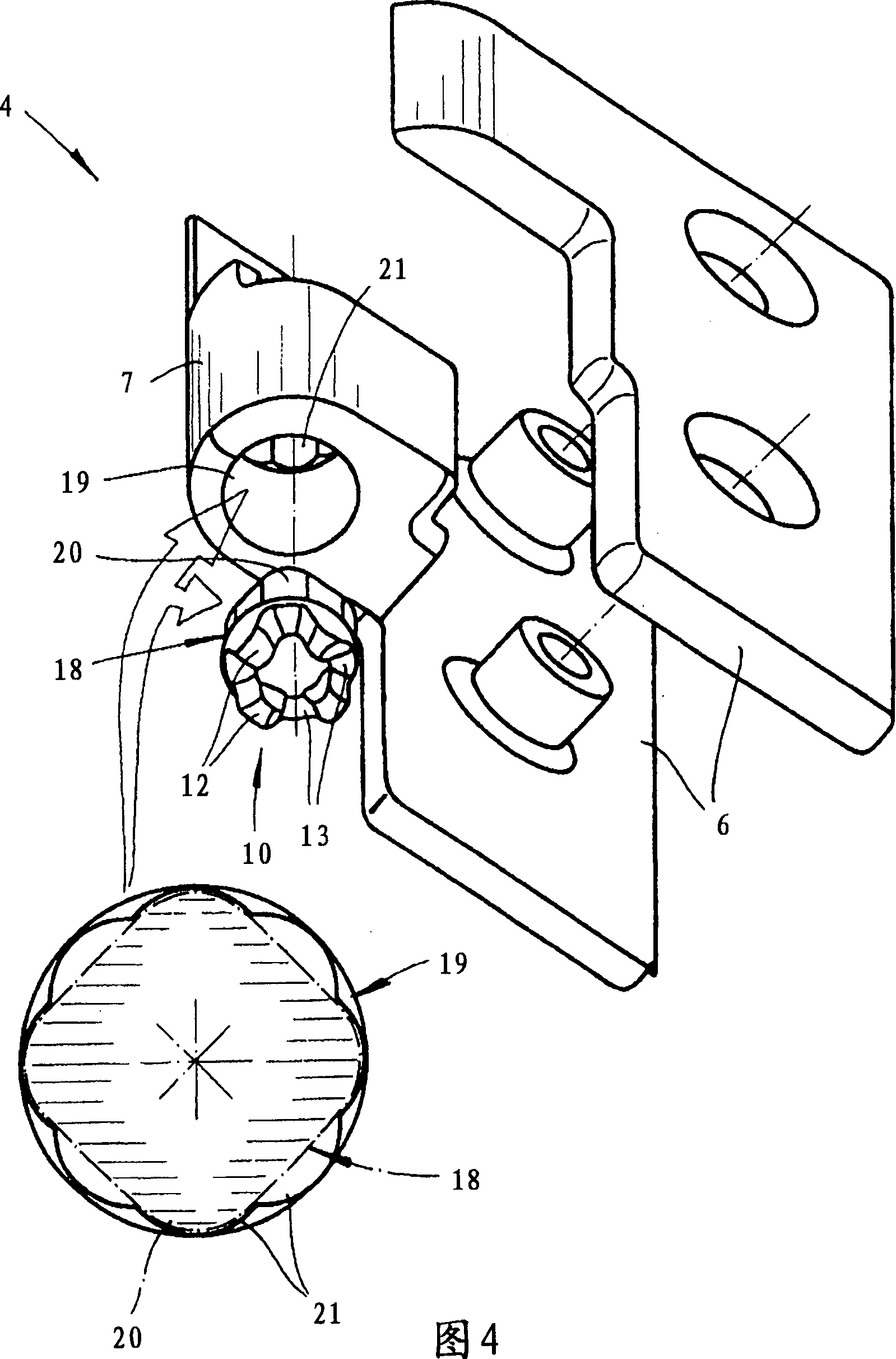
[0018] Shown is a hinge 1 according to the invention, which shows the lower hinge 1 of the device for securing a door leaf 2 in the installed state. The door leaf 2 is in particular made of glass or plastic. The hinge 1 comprises two hinge leaves 4 , 5 which are preferably connected together by a screw pin 3 . Each hinge leaf 4 , 5 includes a fixing plate 6 and a hinge hole 7 . Said fixing plate 6 is used for the door leaf 2 by joining together the two parts comprised by itself, ie housing the door leaf 2 between them (see especially FIGS. 1 and 4 ).

[0019]The hinge 1 according to the invention is provided with a locking mechanism 8 having locking profiles 9, 10 which secure the door leaf 2 in the desired pivoting position, wherein the locking profiles 9, 10 are preferably located at the joints of the two hinges. Pages 4, 5 each above. The locking mechanism 8 is therefore formed in this exemplary embodiment such that it can fix the door leaf in a 45° or 90° position. Acc...


PUM


Abstract

Fitting for fastening a door wing, especially a door wing of a shower partition made of glass, plastic or similar material, with a hinge of two hinge leaves joined together by means of a keybolt, wherein each hinge leaf features a fastening plate and a hinge eyelet. The hinge features a detent mechanism with locking profiles which hold the door wing in the default swing position. The locking profiles are provided on each of the two hinge leaves. The locking profiles are provided on the keybolt.

Description

technical field [0001] The present invention relates to a device for securing a door leaf, in particular a shower door leaf made of glass, plastic or other similar material, with a hinge, preferably two pieces joined together by a keybolt. hinge hinges, wherein each hinge hinge includes a fixing plate and a hinge hole. The hinge includes a locking mechanism with a locking profile, which is provided in two preferred positions, to fix the door leaf in a predetermined pivoting position. Generally, such devices include a lower hinge and an upper hinge respectively supporting the door leaves. The scope of protection of the present invention includes that one of the two hinges has a locking mechanism that fixes the door leaf at a predetermined swing position. In principle, the scope of protection of the present invention also includes that the two hinges described above have this lock The situation of closed institutions. Background technique [0002] A device of the above-ment...

Claims


Application Information

Patent Timeline
IPC IPC(8): E05D11/10E05D5/10E05D5/02A47K3/36E05D5/12E05D7/00
CPCE05Y2900/114E05D7/0018E05D5/0246A47K3/36E05D2007/0461E05D2011/1092E05D5/128E05D11/1078E05D5/10E05D2005/106
Inventor K·米夏拉
Owner FOREMOST INT
Why Eureka
Try Eureka