OADM site
An optical add-drop multiplexing and site technology, applied in wavelength division multiplexing systems and other directions, can solve problems such as inconvenient business operation and maintenance, user loss, capacity expansion, etc., to achieve convenient business operation and maintenance, simple control, and simple expansion operations. Effect
- Summary
- Abstract
- Description
- Claims
- Application Information
AI Technical Summary
Problems solved by technology
Method used
Image
Examples
Embodiment 1
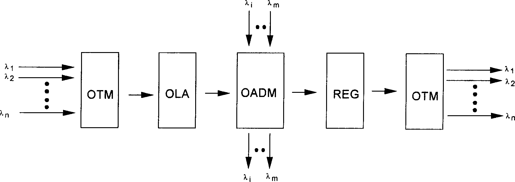
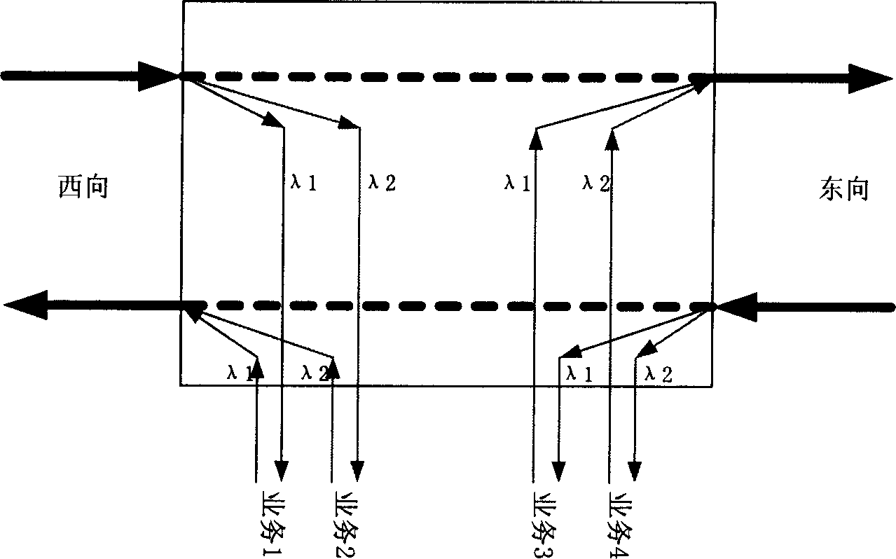
[0037] Such as Figure 4 As shown, the first optical add-drop multiplexing site 10 of the present invention includes the first optical add-drop multiplexing module OADM1, the second optical add-drop multiplexing module OADM2 and the first optical add-drop multiplexing module OADM1 and the second optical add-drop multiplexing module OADM1. The first switching device S10 and the second switching device S11 on the optical path of the service level connection are connected between the two optical add-drop multiplexing modules OADM2. In this embodiment 1, the first and second switching devices S10 and S11 are 2×2 optical switches, and the input and output terminals of the straight-through state are respectively the input and output terminals of the pass-through service, and the other two ports are respectively the expansion input terminal and expansion output terminal.
[0038] On the west link, the input terminal of the through state of the 2×2 optical switch of the first switchi...
Embodiment 2
[0047] Such as Image 6 As shown, the difference between the optical add-drop multiplexing site 20 in Embodiment 2 of the present invention and the optical add-drop multiplexing site 10 in Embodiment 1 is that it is located in the first optical add-drop multiplexing module OADM1 and the second optical add-drop multiplexing module OADM1. The first switching device S20 and the second switching device S21 on the optical path of the pass-through service level connection between modules OADM2 each include a first coupler C1 and a 1×2 optical switch SW1, wherein the input end of the first coupler C1 is a pass-through service The input terminal and one output terminal are connected to one input terminal of the 1×2 optical switch SW1, the output terminal of the 1×2 optical switch SW1 is the pass-through service output terminal, and the other input terminal B of the 1×2 optical switch SW1 is connected to the first coupler The other output terminal A of C1 is respectively an expansion i...
Embodiment 3
[0056] Such as Figure 8 As shown, the difference between the optical add-drop multiplexing station 30 in Embodiment 3 of the present invention and the optical add-drop multiplexing station 20 in embodiment 2 is that it is located in the first optical add-drop multiplexing module OADM1 and the second optical add-drop multiplexing module OADM1. The first switching device S30 and the second switching device S31 on the optical path of the pass-through service level connection between the modules OADM2 replace the 1×2 optical switch with a coupler, each including a second coupler C2 and a third coupler C3, wherein the first The input end of the second coupler C2 is the pass-through service input end, an output end is connected to an input end of the third coupler C3, the output end of the third coupler C3 is the pass-through service output end, and the other end of the third coupler C3 An input terminal D and another output terminal C of the second coupler C2 are capacity expansio...
PUM
 Abstract
Description
Claims
Application Information
 - R&D
- Intellectual Property
- Life Sciences
- Materials
- Tech Scout
- Unparalleled Data Quality
- Higher Quality Content
- 60% Fewer Hallucinations
Browse by: Latest US Patents, China's latest patents, Technical Efficacy Thesaurus, Application Domain, Technology Topic, Popular Technical Reports.
© 2025 PatSnap. All rights reserved.Legal|Privacy policy|Modern Slavery Act Transparency Statement|Sitemap|About US| Contact US: help@patsnap.com


