Valve, especially for a sanitary fitting

A sanitary device, especially a technology, applied in the valve field of sanitary devices, can solve the problem of not being able to distinguish which position the valve is in, whether the nozzle or the sprinkler has been set, etc.

Inactive Publication Date: 2006-12-27
WEIDMANN PLASTICS TECH
View PDF7 Cites 5 Cited by
  • Summary
  • Abstract
  • Description
  • Claims
  • Application Information

AI Technical Summary

Problems solved by technology

It is therefore also not possible for the user to distinguish which position the valve is in or whether the nozzle or sprinkler has been set

Method used


Image

  • Valve, especially for a sanitary fitting
  • Valve, especially for a sanitary fitting
  • Valve, especially for a sanitary fitting

Examples


Embodiment Construction

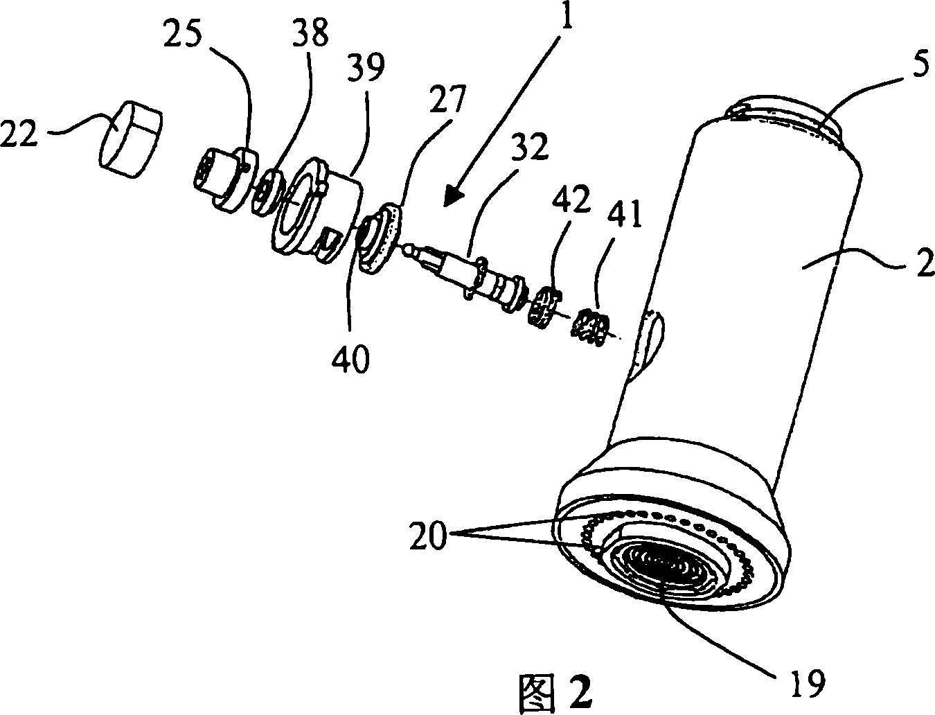
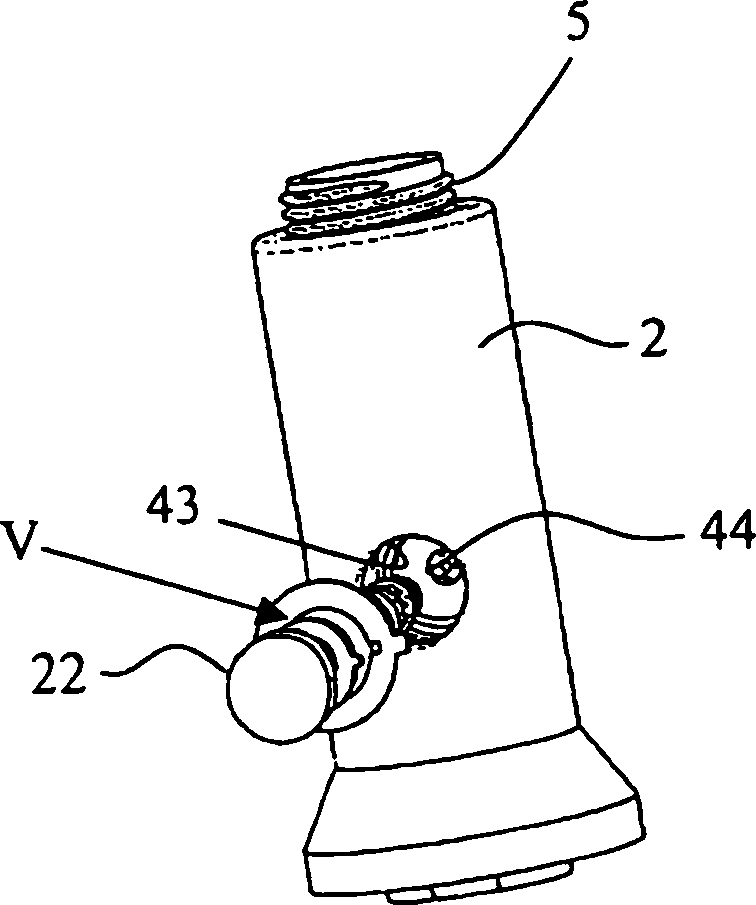
[0034] figure 1 Shown is a spray head 1 with a water delivery tube 3 inside the housing 2, said water delivery tube being provided with a connecting thread 5 at an end protruding from the housing 2 for connecting the spray head 1 to A flexible water hose (not shown here). The spray head 1 is used in particular for a pull-out spray device, wherein the water line is guided in a device such that the spray head 1 can be pulled out by hand.

[0035] The water delivery pipe 3 is sealed relative to the housing 2 by a sealing ring 6 and has a funnel-shaped connecting portion 15 at its front end, which is sealed relative to the water delivery pipe 3 by a sealing ring 16 . A connecting portion 15 connects the water delivery pipe 3 to a jet former 19 known per se. The jet former 19 is inserted centrally in an opening plate 18 which is detachably connected to the housing 2 by means of threads 21 . A plurality of nozzles 20 are arranged annularly in this opening plate 18 for forming a s...


PUM


Abstract

The valve has a valve housing ( 39 ), in which a valve body ( 26 ) is mounted displaceably and preferably rotatably about its longitudinal axis (A). It has at least one valve seat ( 53, 54 ), with which the valve body ( 26 ) interacts. A button ( 22 ) is operationally connected to the valve body ( 26 ) in order to displace the valve body ( 26 ) from a basic position into a working position. The valve body ( 26 ) is controlled in such a way that it is automatically locked releasably in the working position when its displacement from the basic position into the working position takes place.

Description

technical field [0001] The invention relates to a valve, in particular for sanitary installations, said valve having a valve housing in which a valve body is movably mounted and actuating means, said valve housing having at least one valve seat with which the valve body interacts to open and close a fluid passage, the actuation device being operatively connected to the valve body by which the valve body can be moved from A basic position is moved to a working position. Background technique [0002] A valve of this type is known in the prior art, for example from US-A-5,383,604. This valve is a changeover valve for a nozzle. The valve body is movable between two positions. In one position, the access to the jet former is open, and in the other position, the access to the plurality of nozzles forming the injection means is open. A two-armed joystick located below a diaphragm is provided for actuation. Two depressed positions are provided, which are spaced apart from one a...

Claims


Application Information

Patent Timeline
Patent Type & Authority Applications(China)
IPC IPC(8): E03C1/04B05B1/32E03C1/08F16K11/00
CPCF16K31/52416Y10T137/87788
Inventor 亨宁·克斯本亚明·霍德尔
Owner WEIDMANN PLASTICS TECH
Why Eureka
Try Eureka