
Spring wire processing device

A processing device and spring wire technology, applied in the direction of extensible conductors, extensible conductor cables, manufacturing extensible conductors/cables, etc. problem, to ensure the quality of the line

Inactive Publication Date: 2006-12-13
SUZHOU CABLEPLUS PHOTOELECTRIC TECH
View PDF0 Cites 10 Cited by
  • Summary
  • Abstract
  • Description
  • Claims
  • Application Information

AI Technical Summary

Problems solved by technology

However, as the spring wire is applied to more high-end electromechanical equipment and electronic and electrical equipment, the quality requirements for the spring wire are becoming more and more stringent, so that the existing processing equipment cannot meet the quality requirements of the product
Because, when the clamp clamps the two ends of the wire body, it will leave deep clamp marks on the wire body and form obvious bright stripes on the finished product, which will expose the following two shortcomings in the finished product. When the contact parts of the wire body are serious, the wire core in the wire body will be exposed, the product will be scrapped or the outer sheath layer of the wire body will be damaged, which will be unfavorable to the protection of the wire core and affect the service life; the second is the appearance of the wire body. Some people may think that since the clamp marks on both ends of the wire body are caused by too much pressure on the wire body by the clamp, then as long as the clamping force of the clamp on the wire body is moderately relaxed, the pinch marks can be avoided. However, if If the clamp is too loose, it will lose the tube bundle at both ends of the wire body, resulting in poor shaping effect, and eventually the product will be scrapped
[0004] Therefore, based on the above reasons, due to the constraints of the processing equipment, the qualified rate of the finished product of the spring wire cannot be guaranteed (because the product with too serious pinch should be removed), especially restricting the extension of the spring wire to the application field with higher requirements, Although the industry is actively exploring suitable processing devices, there is no corresponding report so far

Method used

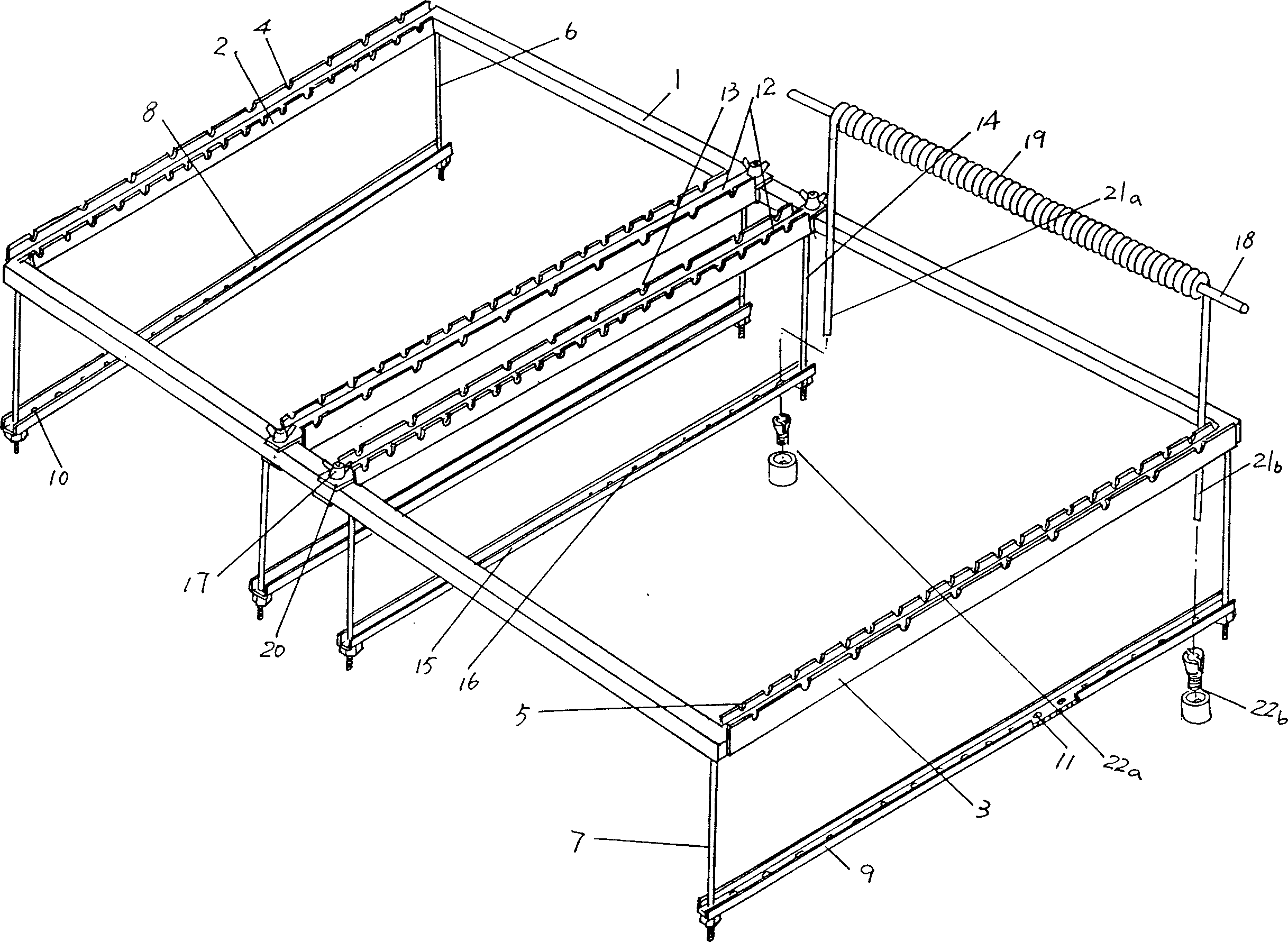

Image

  • Spring wire processing device
  • Spring wire processing device

Examples


Embodiment Construction

[0019] Through the applicant's description of the embodiments below, it will be more helpful to understand the technical essence of the present invention and make the effect of the present invention more manifest, but the embodiments should not be regarded as any limitation to the present invention.

[0020] exist figure 1 In, the applicant provides a bracket 1 which is rectangular, more specifically rectangular, and which is made of stainless steel. The two ends of the bracket 1 are respectively formed with first and second winding rod positioning plates 2 and 3. As shown in the figure, the first and second winding rod positioning plates 2 and 3 adopt a composite structure. The so-called composite structure refers to the first 1. The second rod-winding positioning plate 2,3 is processed into a cross-sectional shape that is U-shaped or horseshoe-shaped, so that the first and second winding rod positioning plates 2,3 each have a pair of wall bodies, and on each wall body The ...


PUM


Abstract

The invention discloses a manufacturing device of spring line in the specific device technological domain of wire cable manufacturing, which comprises the following parts: one rack, at least one couple of first and second bar-winding locating boards on two ends of rack, first and second locating grooves on the first and second locating boards intervally and separately, one couple of first and second booms corresponding to two end parts of first and second bar-winding locating boards extended on the rack, one couple of first and second clamps with two ends fixing on one couple of first and second booms, first and second line holes on the floor of first and second clamps intervally and separately. The invention can't destroy any line bulk of spring through cutting the limit touching part of second rear part and clamp, which guarantees the line quality of spring line.

Description

technical field [0001] The invention relates to a spring wire processing device, which is suitable for processing various spring wires and spiral cables, and belongs to the technical field of special devices for wire and cable processing. Background technique [0002] Since the spring wire has relatively stable linearity, excellent straightening, elastic height, and elastic width, which is convenient for automatic winding, and also has excellent fatigue resistance, flexibility, elasticity, etc., it is widely used. Ordinary spring wires, such as the connecting wires between the handset and the telephone, and the connecting wires for walkie-talkies; the spring wires with higher requirements, such as electrical installation connecting wires for various electromechanical equipment and electronic and electrical equipment; Spring wires are used for connecting wires of electronic and electrical equipment equipped in aircraft, Shenzhou 5 and Shenzhou 6, etc. Therefore, the applicati...

Claims


Application Information

Patent Timeline
IPC IPC(8): H01B13/008H01B13/00H01B7/06
Inventor 詹祖根陈良赵立芬杨金祥
Owner SUZHOU CABLEPLUS PHOTOELECTRIC TECH
Learn More