
Ball bearing device, oscillating weight structure for automatic winding and automatic winding timepiece equipped with the same

A technology of automatic winding and ball bearings, which is applied in the direction of automatic winding, ball bearings, spring ratchet mechanisms, etc., can solve the problems of reducing performance and achieve the effect of preventing mutual adjoining or mutual interference, and relatively stable movement

Inactive Publication Date: 2006-12-13
SEIKO INSTR INC
View PDF0 Cites 12 Cited by
  • Summary
  • Abstract
  • Description
  • Claims
  • Application Information

AI Technical Summary

Problems solved by technology

Reduced initial motion performance due to greater mass and inertia of the thicker cage

Method used


Image

  • Ball bearing device, oscillating weight structure for automatic winding and automatic winding timepiece equipped with the same
  • Ball bearing device, oscillating weight structure for automatic winding and automatic winding timepiece equipped with the same
  • Ball bearing device, oscillating weight structure for automatic winding and automatic winding timepiece equipped with the same

Examples


Embodiment Construction

[0047] Certain preferred embodiments of the present invention will hereinafter be described with reference to preferred examples shown in the accompanying drawings.

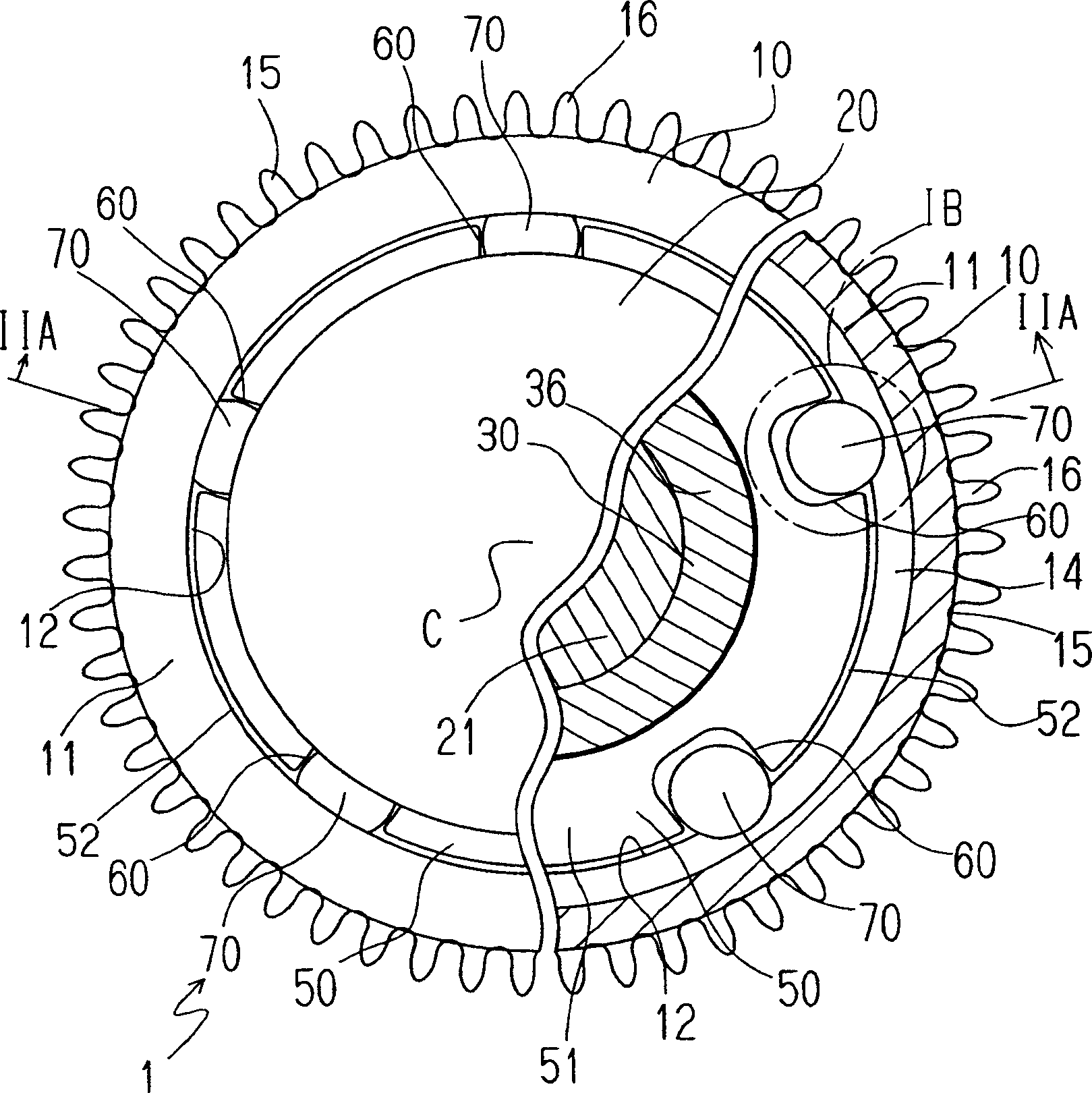
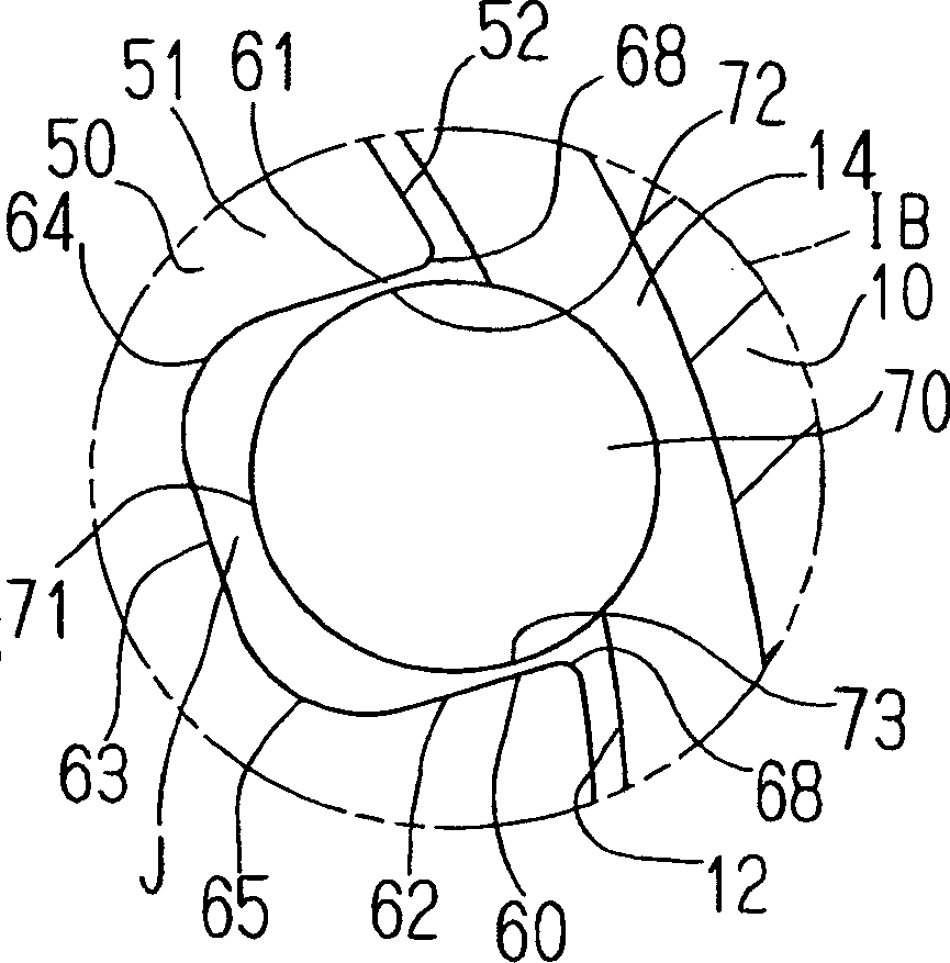
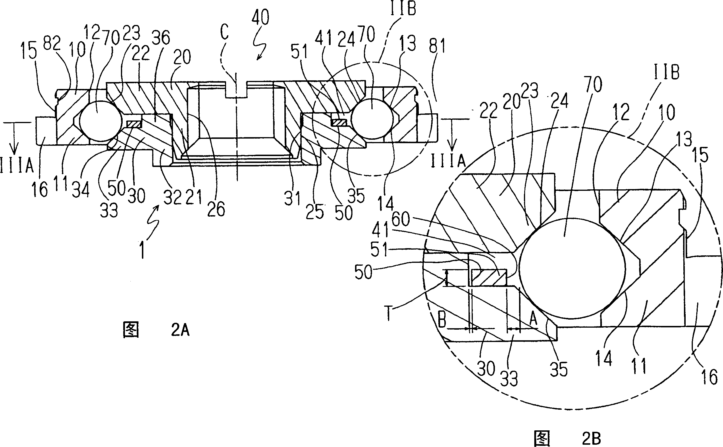
[0048] Figure 1A , 1B , 2A and 2B show a ball bearing device 1 of a preferred example of the present invention having an outer ring 10 , an inner ring 40 including an inner ring main body 20 and a retaining ring 30 , a cage 50 and balls 70 . In the examples described below, a ball bearing device having five balls 70 supported at equal intervals by a holder 50 and having a diameter of about 0.6 mm is described as an example considering that the ball bearing device is used for an automatic winding mechanism of a timepiece. . Those ball bearing arrangements corresponding to those described are therefore specified by the dimensions of different gaps or the like. The dimensions of the various segments may vary significantly if the ball bearing arrangement is of a different size or use.

[0049] The outer ring 10 ...


PUM


Abstract

A ball bearing device includes an outer ring, an inner ring, a plurality of balls disposed between the outer ring and the inner ring regulated in the radial direction, a retainer provided with a plurality of recessed sections in the circumferential direction at intervals each having an opening in the outer periphery for holding respective one of the balls in the circumferential direction at intervals, and rotatably fitted to the inner ring. Each of the recessed sections of the retainer is formed deeper and wider than the ball in a bottom wall section of the recessed section so that a gap remains between a bottom wall surface of the recessed section and a surface of the ball radially regulated between the outer ring and the inner ring, and can be abut on the ball with the surface opposing to the ball in the circumferential direction in surface sections adjacent to the opening.

Description

technical field [0001] The present invention relates to a ball bearing device suitable for a self-winding timepiece, and a self-winding timepiece equipped with a ball bearing device. Background technique [0002] Ball bearing arrangements for timepieces are known which have an outer ring, an inner ring and a plurality of balls arranged between the outer ring and the inner ring under radial constraints, provided with access to the outer periphery for holding A plurality of circumferentially spaced concave segments of circumferentially spaced balls rotates a cage mounted on an inner ring (for example, Patent Documents 1 and 2). [0003] This type of conventional ball bearing device 101 includes an outer ring 110, an inner ring 140 including an inner ring body 120 and a retaining ring 130, a cage 150 and balls 170, as shown in FIGS. 14, 14A, 14B, 15A and 15B. [0004] The outer ring 110 includes a cylindrical or circular main body 111, a pair of inclined circular surfaces 113 ...

Claims


Application Information

Patent Timeline
Patent Type & Authority Applications(China)
IPC IPC(8): G04B31/00G04B5/00G04B5/02G04B5/18F16C19/02
CPCF16C19/163G04B5/184F16C33/41G04B31/0123G04B5/19F16C19/166
Inventor 海老明
Owner SEIKO INSTR INC
Learn More