Automatic camera alarm device of anti-theft door

An automatic camera and alarm device technology, which is applied to anti-theft alarms, anti-theft alarm mechanical start, alarms, etc., can solve the problems of not being able to record the scene of the crime and not being able to call the police, so as to facilitate the detection of crimes and stop theft. Effect

Inactive Publication Date: 2006-11-29
许洪文
View PDF0 Cites 1 Cited by
  • Summary
  • Abstract
  • Description
  • Claims
  • Application Information

AI Technical Summary

Problems solved by technology

When the anti-theft door is opened by a thief with a hard and sharp tool, it is impossible to call the police, let alone record the thief's facial features and crime scene

Method used


Image

  • Automatic camera alarm device of anti-theft door

Examples


Embodiment

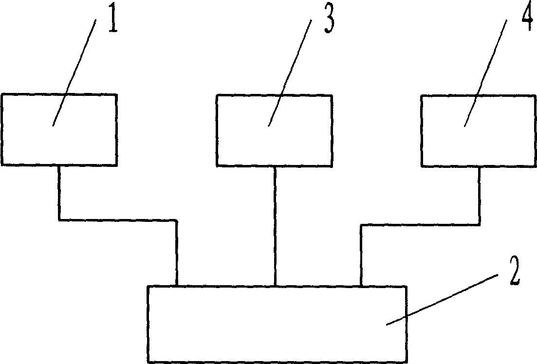
[0013] As shown in the accompanying drawings, the device is composed of an infrared distance measuring device 1, a control box 2, a camera device 3 and an alarm 4. connected to the control circuit. The infrared distance measuring device 1 adopts an infrared transmitting receiver. The camera device 3 has a communication interface and can be a digital camera or a video camera. The control box 2 is equipped with a control circuit, which is provided with a function switch, which can control and start the alarm 4 and the camera 3 according to the signal change of the infrared distance measuring circuit.

[0014] The infrared ranging device 1 is placed on the inner side of the door, constantly transmits and receives ranging signals to the opposite wall in the door, and continuously transmits data to the control circuit. Camera 3 is installed in the position facing the door indoors. When the anti-theft door was accidentally opened, the ranging signal became abnormal, and when the ...


PUM


Abstract

An automatic video-shooting and alarm device of burglar-proof door is composed of infrared distance-measuring unit, video-shooting unit, control circuit and alarm. It features that infrared distance-measuring unit and video-shooting unit as well as alarm are separately connected to control circuit by line.

Description

technical field [0001] The invention relates to an automatic camera alarm device for an anti-theft door. Background technique [0002] In real life, household anti-theft doors usually only have anti-prying, anti-smashing, peeping, and intercom functions. When the anti-theft door is opened by a thief with a hard and sharp tool, it is impossible to call the police, let alone record the thief's facial features and crime scene. Contents of the invention [0003] Aiming at the shortcomings of the existing anti-theft door, the invention provides an automatic camera alarm device for the anti-theft door that can alarm and record the scene when the door is opened. [0004] The present invention adopts following technical scheme: [0005] The device is composed of an infrared distance measuring device, a control circuit, a camera and an alarm, and the infrared distance measuring device, the camera and the alarm are all respectively connected with the control circuit through lines....

Claims


Application Information

Patent Timeline
Patent Type & Authority Applications(China)
IPC IPC(8): G08B13/08G08B15/00
Inventor 许洪文许福运
Owner 许洪文
Why Eureka
Try Eureka