Automatic engine halt system

An engine stop and engine technology, applied in engine components, engine control, engine starting, etc., can solve the problems of restart, reduce the service life of centrifugal clutch, instability, etc., and achieve the effect of small wear and tear

Inactive Publication Date: 2006-11-29
DENSO CORP
View PDF0 Cites 0 Cited by
  • Summary
  • Abstract
  • Description
  • Claims
  • Application Information

AI Technical Summary

Problems solved by technology

Therefore, the centrifugal clutch has the disadvantage that the engine 100 needs to be restarted when the centrifugal clutch is disengaged and the engine 100 stops or rotates in the reverse direction after the engine 100 once stopped.
This can cause instability and reduce the life of the centrifugal clutch during restarting the engine 100

Method used


Image

  • Automatic engine halt system
  • Automatic engine halt system
  • Automatic engine halt system

Examples


Embodiment Construction

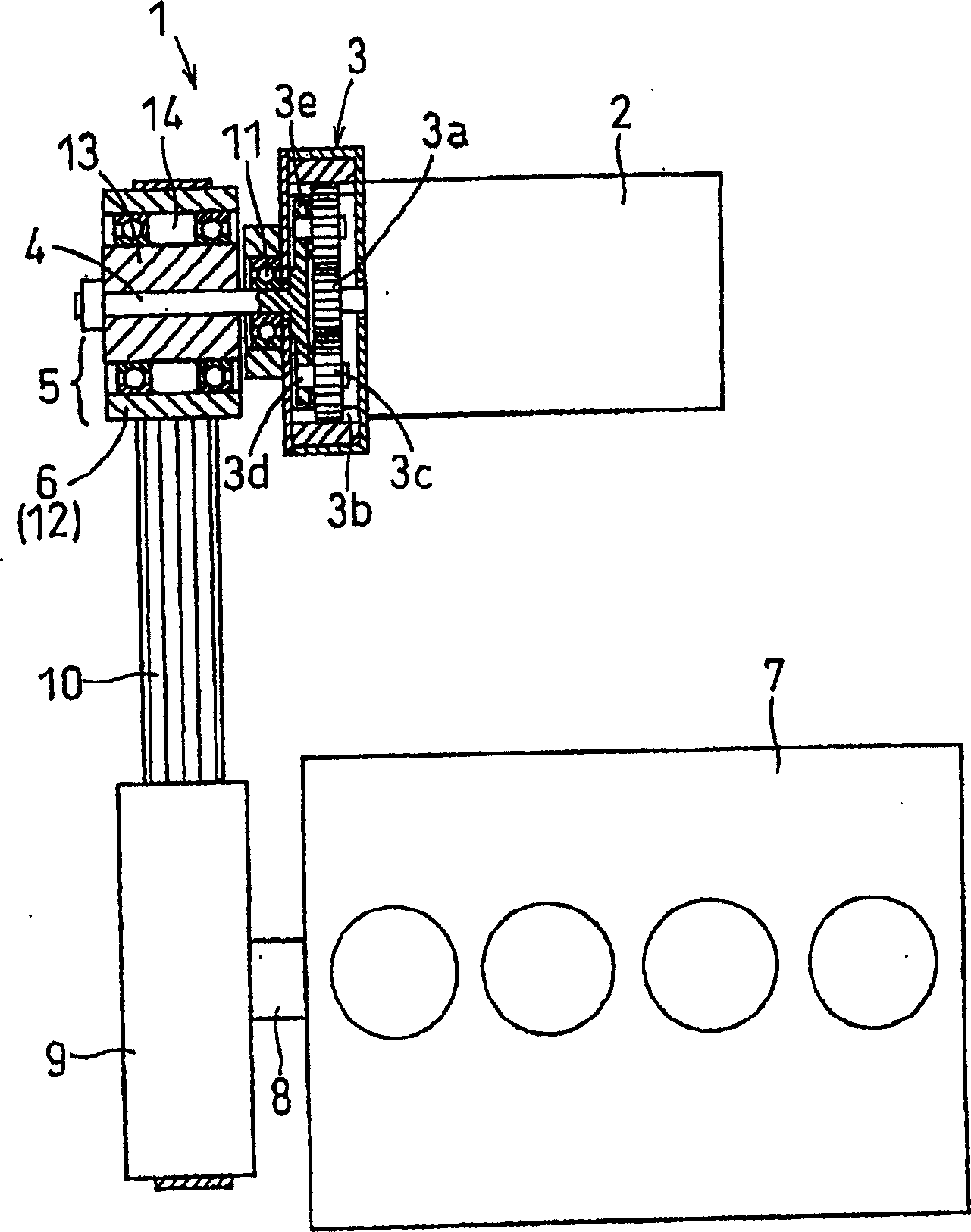
[0027] Referring to the drawings, like reference numerals denote like parts throughout the several views, in particular figure 1 An engine starter 1 as an example of a first embodiment of the present invention, which will be described below, is shown, which is commonly used to start an internal combustion engine of a motor vehicle.

[0028] Engine starter 1 mainly comprises electric motor 2 (also refers to starter motor below), speed reducer 3, output shaft 4, the centrifugal clutch 5 that is connected with output shaft 4 and starter pulley 6. The speed reducer 3 is used to reduce the speed of the starter motor 2 . The output shaft 4 transmits the torque output by the reducer to the starter pulley 6 through the centrifugal clutch 5 . The starter pulley 6 is connected with the crankshaft pulley 9 through a belt 10 . The crank pulley 9 is connected to the crankshaft 8 of the engine 7 .

[0029] The starter motor 2 is implemented by energizing an armature installed in a known ...


PUM


Abstract

The present invention provides an engine starter equipped with a centrifugal clutch. The clutch includes an inner clutch driven in rotation by the torque of the starter motor, an outer clutch always connected to the engine crankshaft, and rollers arranged to abut against the outer speed of the clutch. The speed outside the clutch, which uses centrifugal force to push the rollers away from the inside of the clutch, creating an oil film between them, is set higher than the speed inside and outside the clutch when the starter motor is spinning under no-load conditions. In this way, direct contact between the rollers and the inside of the clutch or indirect contact between them via an oil film can be achieved when, for example, the engine has been stopped and the starter motor is switched on again, thereby increasing the service life of the centrifugal clutch and Reliability of engine starters.

Description

technical field [0001] The present invention relates generally to an improved construction of an engine starter equipped with a centrifugal clutch for transmitting torque from a starter motor to an internal combustion engine of a motor vehicle, and more precisely to such a Engine starter with minimized unwanted mechanical impact on centrifugal clutch. Background technique [0002] FIG. 5 shows a typical example of an engine starter 150 equipped with a starter pulley 130 always connected with a crankshaft pulley 110 of the engine 100 through a belt 120 . The starter pulley 130 has a centrifugal clutch incorporated therein. [0003] As shown in FIG. 6 , the centrifugal clutch is composed of an outer portion 140 , an inner portion 160 and rollers 170 interposed between the outer portion 140 and the inner portion 160 . The outer portion 140 is integrally formed with the starter pulley 130 . The interior 160 is driven by a starter motor 150 . When the inner 160 is rotated by ...

Claims


Application Information

Patent Timeline
Patent Type & Authority Applications(China)
IPC IPC(8): F02N11/10F02D17/00F02D29/02F02N15/00F02N15/02F02N15/08F16D43/14F16D43/24
CPCF02N15/026F16D43/24
Inventor 春野贵誉一斋藤干男
Owner DENSO CORP
Why Eureka
Try Eureka