Mechanical device for removing gear-hobbing burr

A mechanical device and burr technology, applied in the direction of mechanical equipment, components with teeth, gear teeth, etc., can solve the problem of difficult to remove burrs, and reduce the process of deburring by fitters or end faces of lathes, reducing production. cost, the effect of improving production efficiency

Inactive Publication Date: 2006-11-29
GUIZHOU QUNJIAN PRECISION MACHINERY
View PDF0 Cites 2 Cited by
  • Summary
  • Abstract
  • Description
  • Claims
  • Application Information

AI Technical Summary

Problems solved by technology

[0006] 2) Burrs are difficult to remove
But this method also has its obvious shortcomings: the car removes the burrs on the end face of the gear, but makes the burrs turn into the tooth grooves, and finally the fitter has to use a copper wire brush to remove the burrs in the tooth grooves

Method used


Image

  • Mechanical device for removing gear-hobbing burr
  • Mechanical device for removing gear-hobbing burr
  • Mechanical device for removing gear-hobbing burr

Examples


Embodiment Construction

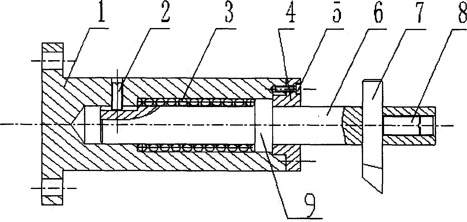
[0024] The embodiment of the present invention: make the base 1, the spring 3, the flange 4, the sliding rod 6, the burr 7 and other parts, according to figure 1 Assemble as shown. First, put the spring 3 on the sliding rod 6 and insert it into the base 1. The two ends of the spring 3 rest on the shoulder 9 and the inner hole step of the base 1, and screw the anti-rotation screw 2 into the base 1. Tighten it in the groove of the sliding rod 6; then, connect the flange 4 with the base 1 with the connecting screw 5; finally, insert the deburring knife 7 into the square hole of the sliding rod 6, and adjust the extension of the deburring knife 7. Use the compression screw 8 to fix the length.

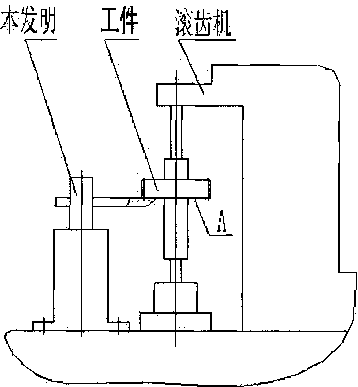
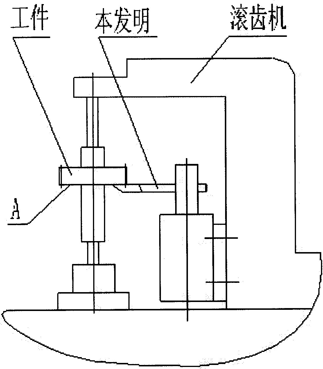
[0025] When in use, the present invention is fixed on the gear hobbing machine, so that the deburring knife 7 is close to the cutting surface A of the workpiece, and the deburring knife 7 can remove burrs while hobbing the gear.


PUM


Abstract

A mechanical structure for removing the burr from hobbed gear is composed of a base, a burr removing cutter, and a slide rod with a shoulder, a spring sleeving on it, a square hole on its end face for installing said cutter, an axial screw hole for installing press screw, and an axial slot for the anti-rotating screw.

Description

Technical field: [0001] The invention relates to a mechanical device for removing hobbing burrs in gear processing. Background technique: [0002] Gears are important basic parts in mechanical products. Gear hobbing is the most commonly used machining method for straight and helical involute cylindrical gears. During gear hobbing, gear hobbing burrs are often unavoidable on the end face of the gear in the direction of the hob. [0003] For hobbing burrs, they must be removed. Because the burrs will directly affect the working accuracy and product performance of the gears, especially those gears with clear and higher requirements on the meshing noise, the hobbing burrs must be completely removed, otherwise the meshing noise index is difficult to meet the requirements of use. [0004] At present, most manufacturers use the method of fitter hair removal. This method has obvious disadvantages: [0005] 1) The labor intensity is very high and the work efficiency is very low. It is nec...

Claims


Application Information

Patent Timeline
Patent Type & Authority Applications(China)
IPC IPC(8): B23F19/00
Inventor 石年平
Owner GUIZHOU QUNJIAN PRECISION MACHINERY
Why Eureka
Try Eureka