
System and method of gymnastic robot

A robot system and robot technology, applied in the directions of manipulators, toys, automatic toys, etc., can solve the problems of increasing the difficulty of motion control, increasing the load, and destroying the symmetry of the system.

Inactive Publication Date: 2006-11-29
INST OF AUTOMATION CHINESE ACAD OF SCI
View PDF0 Cites 3 Cited by
  • Summary
  • Abstract
  • Description
  • Claims
  • Application Information

AI Technical Summary

Problems solved by technology

However, the quality of the reduction mechanism increases the load of the gymnastics robot, and the motor and the reduction mechanism are installed on one side of the connecting rod, which destroys the symmetry of the system, and the actual system parameters are far from the ideal model. The above characteristics increase the realization Difficulty of motor control

Method used


Image

  • System and method of gymnastic robot
  • System and method of gymnastic robot

Examples


Embodiment Construction

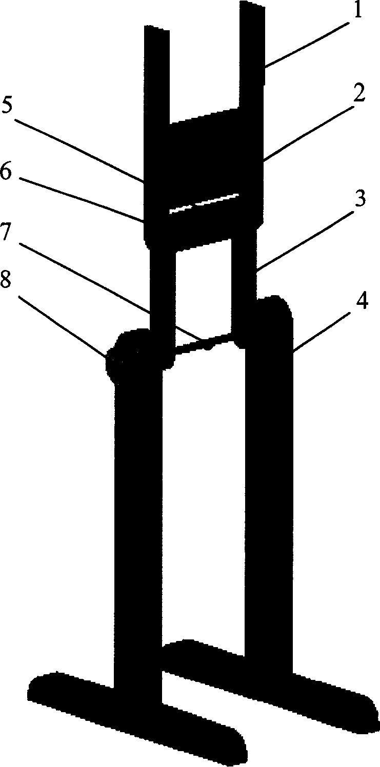
[0017] figure 1 , the gymnastics robot consists of a leg 1, a torso 2, an arm 3, a bracket 4, a motor 5, a shoulder angle sensor 6, a horizontal bar 7, and a wrist angle sensor 8.

[0018] The motor, shoulder angle sensor, arm and horizontal bar are fixed together, which is equivalent to the first link in the topology. One end (horizontal bar) of the first connecting rod is provided with a rotating bearing between the support, so that the first connecting rod can freely rotate around the axis of the horizontal bar. The wrist angle sensor is connected with the horizontal bar and installed on the support mechanism to measure the angle of rotation of the wrist, and the angular velocity can be calculated through the time differential of the angle.

[0019] The legs are fixed to the torso with no relative motion between them, acting as the second link in the topology. A rotating bearing is installed between the other end of the first connecting rod (the output shaft of the motor ...


PUM


Abstract

A gymnastic robot able to simulate the gymnastic actions is composed of legs, trunk, arms, supporting frame, motor, shoulder angle sensor, horizontal bar and wrist angle sensor.

Description

technical field [0001] The invention relates to a gymnastics robot system, which belongs to an underactuated robot, in particular to a gymnastics robot system and method. Background technique [0002] The gymnastics robot (Acrobot) is topologically composed of two connecting rods, a free-rotating joint of the wrist grasping the bar and a driving joint of the shoulder. The two connecting rods move in the same vertical plane. It belongs to a typical under-actuated robotic system, that is, the number of driving joints is less than the number of degrees of freedom of the system. The main feature of the system is its simple structure, which is convenient for the overall dynamic analysis and experiment, but the relationship between the driving torque and the state of the two connecting rods is very complicated, which is convenient for theoretically investigating some nonlinear control methods such as optimal control, The effectiveness of methods such as robust control, adaptive c...

Claims


Application Information

Patent Timeline
IPC IPC(8): A63H13/00B25J11/00
Inventor 赵东斌易建强
Owner INST OF AUTOMATION CHINESE ACAD OF SCI
Learn More