
Method for dynamic selection of array antenna structure

An array antenna, dynamic technology, applied in the direction of antenna, antenna array, diversity/multi-antenna system, etc., can solve the problems of inability to receive, waste of resources, difficult operation, etc., to achieve improved reliability, improved performance, and great flexibility. Effect

Active Publication Date: 2006-11-15
WUHAN HONGXIN TELECOMM TECH CO LTD +1
View PDF0 Cites 9 Cited by
  • Summary
  • Abstract
  • Description
  • Claims
  • Application Information

AI Technical Summary

Problems solved by technology

[0004] The above two methods of determining the new array antenna structure have different defects and problems: for the first method, since the original array antenna structure needs to be abandoned and a completely new array antenna structure is completely reconstructed, it will not only bring operational problems Difficulty and waste of resources, and there may be problems that receivers are not compatible in different situations, so it is difficult to be applied in practice
In other words, if a new array is formed directly based on the existing array elements with fixed positions to receive the arriving signal, it is easy to have a reception blind zone, that is, a certain area cannot receive the arriving signal all the time, which leads to the failure of the receiver system to recover source, not working
It can be seen that the fixed array antenna structure selection scheme can easily cause a blind area for receiving signals, that is, the receiver cannot receive and detect signals corresponding to a certain angle of arrival, resulting in communication failures.

Method used


Image

  • Method for dynamic selection of array antenna structure
  • Method for dynamic selection of array antenna structure
  • Method for dynamic selection of array antenna structure

Examples


Embodiment Construction

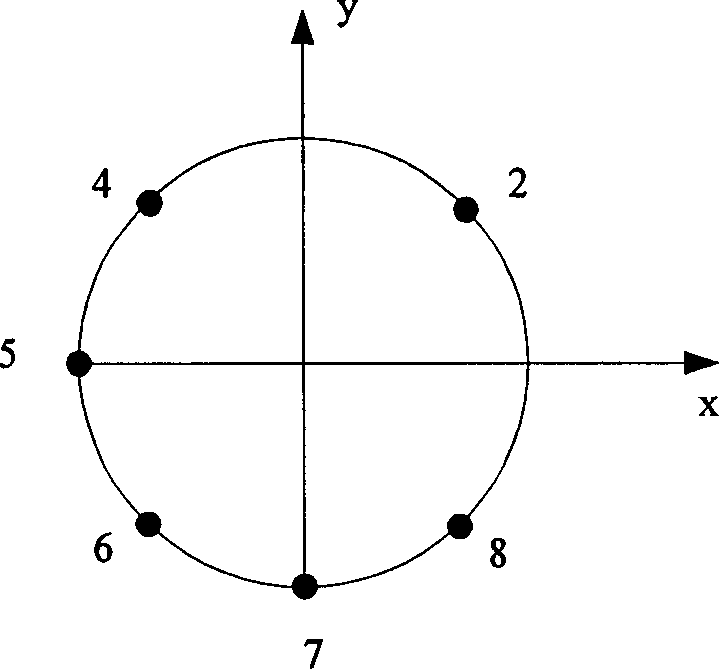
[0017] The core idea of ​​the present invention is: select some array elements from all the array elements of the selected basic array antenna to form different array antenna structures, and dynamically select different array antenna structures according to the change of transmission time interval and / or time slot Receive and detect user signals.

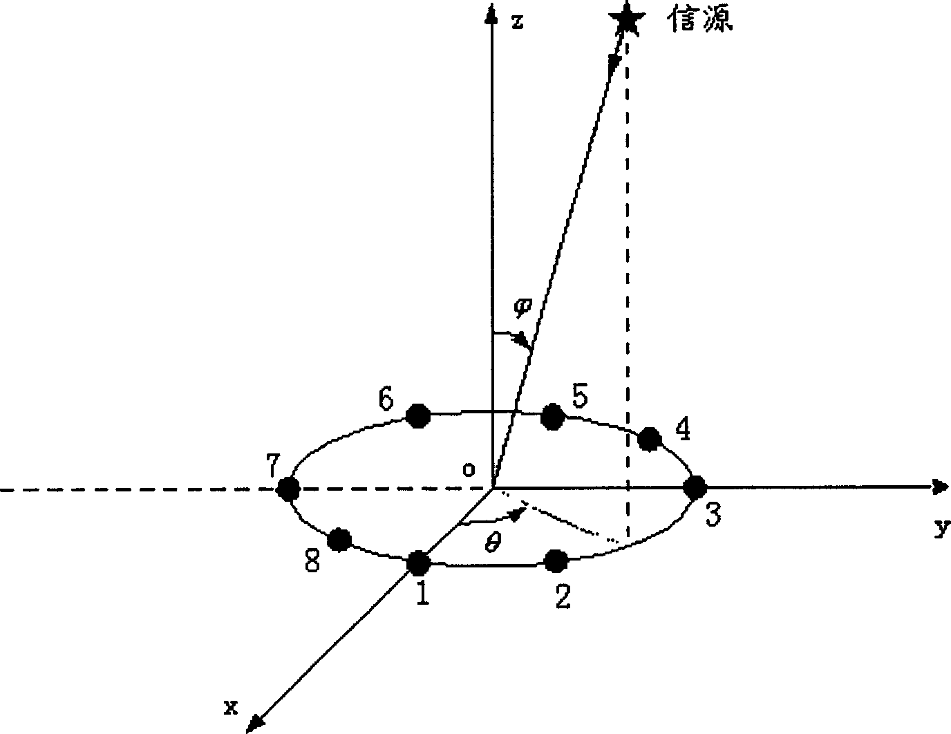
[0018] Here, the existing array antenna is used as the basic array antenna, and the existing array antenna refers to linear array antennas, circular array antennas, etc. of 4 array elements, 8 array elements, and 16 array elements; the selected part of the array elements is mainly According to the processing capability of the system and / or the number of users currently connected, first determine the number of array elements to be selected, and then determine which array elements to select. The specific selection of which array elements is arbitrary, for example: for an 8-element uniform circular array antenna The structure is determ...


PUM


Abstract

The invention discloses the method of dynamic choosing array antenna structure, the basic array antenna is chosen and the needed array element number can be determined, the determining number of the array element can be elected from all the array element of the basic array antenna to form the array antenna structure, the existing array antenna structure is adopted to perform the receiving and the testing of the signal, the method also includes: if the transferring time interval sum and the time gap position is changing can be judged, if it is the true, the determining number of the array element would be elected again from all the array element of the basic array antenna to from the new array antenna structure, and the new array antenna structure is adopted to perform the receiving and the testing of the signal, if it is the fake, the judging continues. The invention has many merits such as the briefness, agility, every array duck receiving the reaching signal more reasonable and the improvement of the receiving the signal of the array antenna.

Description

technical field [0001] The invention relates to array antenna technology, in particular to a method for dynamically selecting an array antenna structure. Background technique [0002] In existing Time Division Synchronous Code Division Multiple Access (TD-SCDMA) systems, most base stations use array antennas to receive and transmit user signals. The so-called array antenna is composed of multiple antenna units according to a certain distribution method, which is used to improve the performance of the antenna system in mobile communication. Each antenna unit in the array antenna is an independent unit, and each antenna unit is also called an array element. , each antenna unit can be an omnidirectional antenna or a directional antenna, and the distribution of all antenna units can be linear, circular, planar or three-dimensional. The array antenna technology is to complete the reception and transmission of user signals in various environments through the mutual cooperation be...

Claims


Application Information

Patent Timeline
Patent Type & Authority Applications(China)
IPC IPC(8): H04B7/26H01Q21/00
CPCH01Q3/242H01Q21/205H04B7/02H04B7/08H04L1/02
Inventor 徐铁铸李峰康绍莉
Owner WUHAN HONGXIN TELECOMM TECH CO LTD
Learn More