
Operation mechanism

A technology of operating mechanism and operating part, applied in the direction of contact operating mechanism, contact operating parts, mechanical equipment, etc., can solve the problems of difficulty in arousing the desire to buy, lack of novelty, and monotonous appearance.

Inactive Publication Date: 2006-11-08
MITSUBISHI ELECTRIC CORP
View PDF3 Cites 7 Cited by
  • Summary
  • Abstract
  • Description
  • Claims
  • Application Information

AI Technical Summary

Problems solved by technology

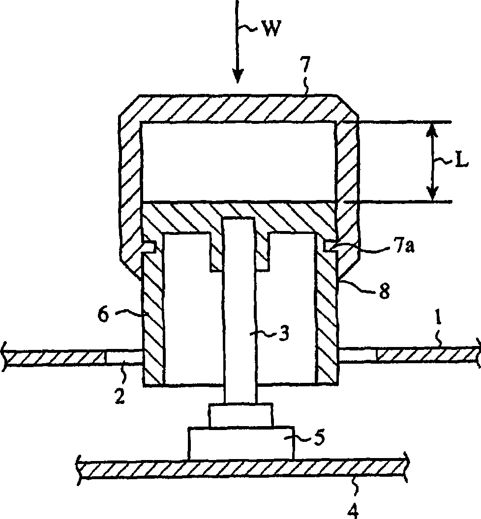
[0007] What these operating parts have in common is that a predetermined component is damaged during a collision to reduce the protrusion of the operating part. However, since the main part of the operating part exposed outside the panel is only one component, the appearance is monotonous and visually lacking. Novelty, it is difficult to arouse the desire to buy

Method used


Image

  • Operation mechanism
  • Operation mechanism
  • Operation mechanism

Examples


Embodiment Construction

[0019] In order to further describe the present invention in detail, preferred modes for implementing the present invention will be described below with reference to the accompanying drawings.

[0020] Implementation form 1:

[0021] Embodiment 1 of the present invention will be described below.

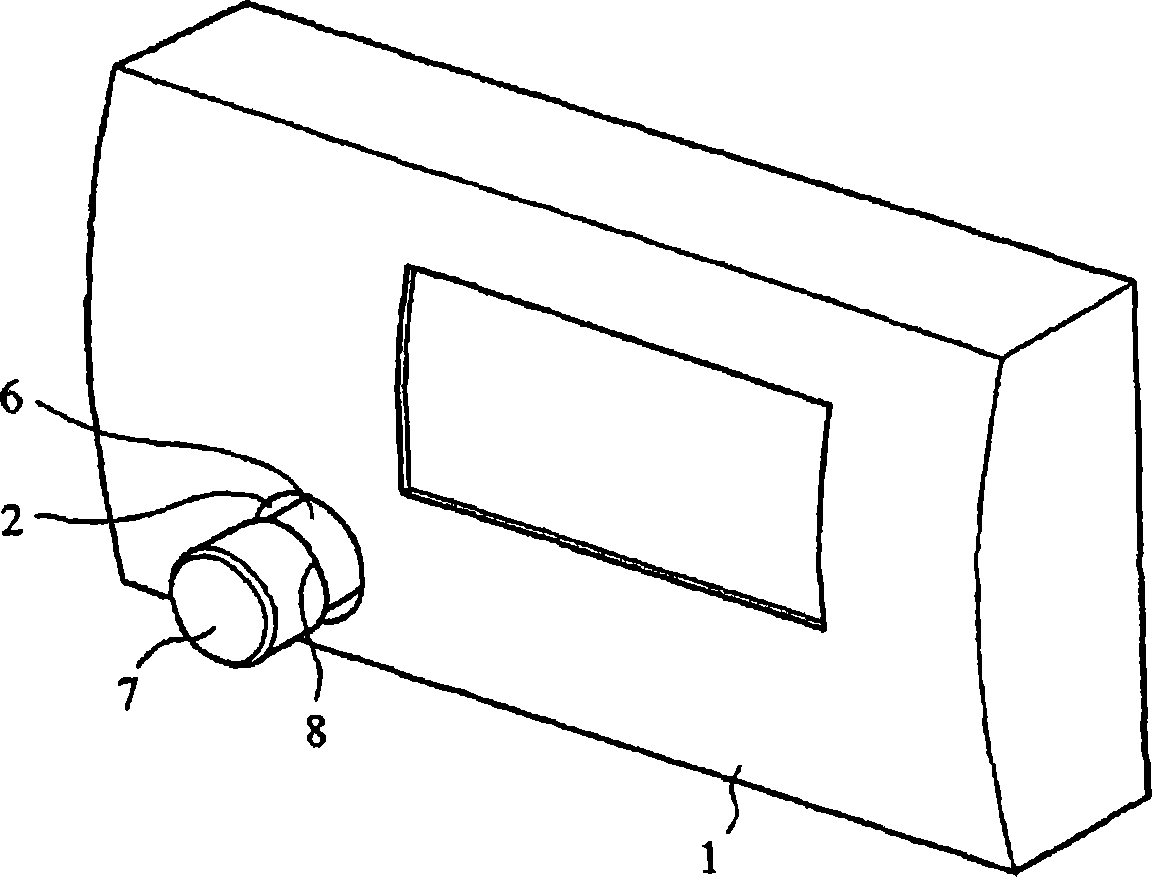
[0022] figure 1 In the front panel 1, a through hole 2 larger than the outer diameter of the operation part is formed, and an operation shaft 3 is provided in the through hole 2. The operating shaft 3 is integrally formed with an operating device 5 fixed to a base plate 4 arranged inside the front panel 1 . The operating shaft 3 can be moved in the axial direction and can be rotated. For example, a push-in encoder can be illustrated as the operating device 5 . In addition, the axial movement operation of the operation part can be switched on and off, and the volume can be adjusted by the rotation operation of the operation part. The front panel 1 may be a front panel of a vehicl...


PUM


Abstract

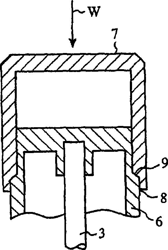
An operation mechanism, comprising a shaft side operating part (6) fitted to an operating shaft (3), an auxiliary operating part (7) fittedly engaged with the shaft side operating part (6) through an engagement means (7a) disengaged when impact is applied thereto to form an operating part, and a boundary part (8) between the both operating parts exposed to the outside of a front panel when the auxiliary operating part (7) in combination with the shaft side operating part (6) is installed on the operating shaft (3).

Description

(1) Technical field [0001] The present invention relates to a shock-absorbable operating mechanism provided, for example, on the front panel of a vehicle stereo, DVD, etc. (2) Background technology [0002] In order to improve the safety of passengers in the front seats in the event of a vehicle collision, for various electrical equipment assembled on the front panel of the vehicle compartment, standards have been established that no protrusions such as operating parts will cause danger to the human body during a collision, and measures have been taken to ensure that the collision various measures of security. [0003] For example, there are the following various structures and the like. (1) A structure in which a damaged part is provided on the knob, and when a large force is applied, the damaged part is crushed, thereby moving the knob (for example, refer to Patent Document 1); The through-shaft hole on the shaft has a structure in which a shock-absorbing member that can...

Claims


Application Information

Patent Timeline
Patent Type & Authority Applications(China)
IPC IPC(8): H01H3/02
CPCH01H3/08H01H2003/026H01H2003/085Y10T74/2084
Inventor 矢桥弘行山本知
Owner MITSUBISHI ELECTRIC CORP
Learn More