Motor-driven throttle valve control device for internal combustion engine
A motor drive and control device technology, which is applied in engine control, machine/engine, mechanical equipment, etc., can solve the problem of shaft length and achieve the effect of shortening the configuration space
- Summary
- Abstract
- Description
- Claims
- Application Information
AI Technical Summary
Problems solved by technology
Method used
Image
Examples
Embodiment 1
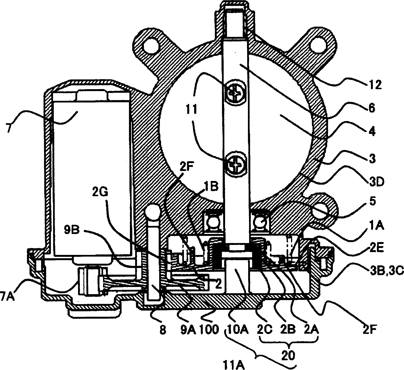
[0027] The outer ring of the ball bearing 5 is fixed to the throttle body 3 , and the throttle shaft 6 is fixed to the inner ring of the same ball bearing 5 .
[0028] The other end of the throttle shaft 6 is held by a slide bearing 13 so as to be slidable with respect to the throttle body 3 . The throttle valve 4 is fixed on the throttle shaft 6 with the valve locking screw 11 .
[0029] In this way, the throttle valve 4 is rotatably arranged in the intake passage formed inside the hole wall 3D of the throttle body 3 .
[0030] The throttle gear 2 is fixed to the ball bearing 5 side end of the throttle shaft 6 .
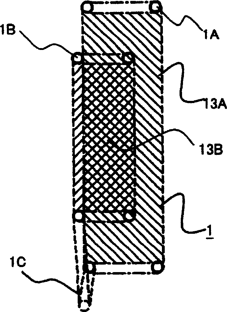
[0031] The spring 1 (1A, 1B) is held on a shaft around the throttle shaft 6 . The rotational force of the throttle gear 2 is transmitted from a motor gear 7A fixed to an output shaft of the motor 7 via an intermediate gear 9 rotatably held on a gear shaft 8 .
[0032] In this embodiment, a brush-type DC motor is used as the motor 7, but a driver capable of genera...
Embodiment 2
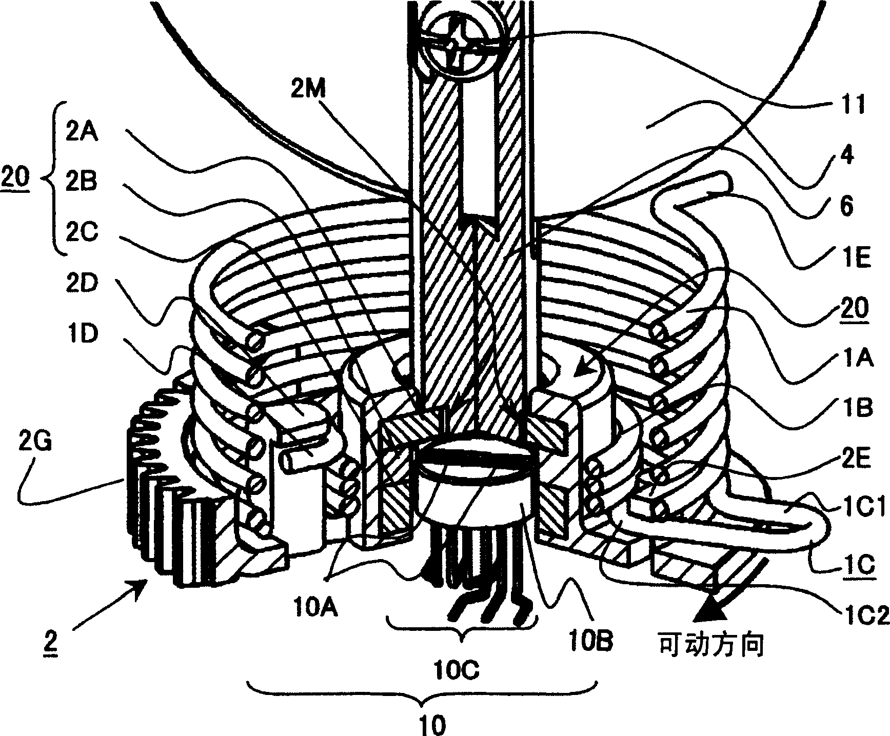
[0087] Figure 11 Example 2 of the present invention is shown. relative to the above Figure 8 In terms of (a), in this embodiment, the spring with a small diameter is used as the return spring 1A, and the spring with a large diameter is used as the default spring 1B.
[0088] At this time, the hook-shaped hook portion 1E, which is the open end of the return spring 1A having a small diameter, is engaged with the locking portion 3E formed on the throttle body 3 .
[0089] On the other hand, a hook-shaped hook portion 1D, which is an open end of a default spring 1B having a large diameter, is hooked to a locking protrusion 2D formed on the throttle gear 2 .
[0090] if from Figure 11 At the default opening position, power on the motor and rotate the throttle gear 2 counterclockwise, then the locking protrusion 2D of the throttle gear 2 will rotate counterclockwise along with the hook-shaped hook part 1D located at one end of the default spring 1B. At this time, the short co...
Embodiment 3
[0096] Figure 12 Example 3 of the present invention is shown. relative to the above Figure 8 In terms of (a), in this embodiment, the spring engaging end surface 2E is formed on the outer side of the spring with a large diameter, so that the spring engaged on the short connecting arm portion 1C1 of the spring hook portion 1C is engaged with the spring formed on the throttle gear 2. End face 2E.
[0097] In this configuration, since one part of the short connecting arm portion 1C1 of the snap hook portion 1C can also serve as two locking portions, there is an advantage that the shape of parts other than the snap hook portion 1C can be freely set.
PUM
 Abstract
Description
Claims
Application Information
 - R&D
- Intellectual Property
- Life Sciences
- Materials
- Tech Scout
- Unparalleled Data Quality
- Higher Quality Content
- 60% Fewer Hallucinations
Browse by: Latest US Patents, China's latest patents, Technical Efficacy Thesaurus, Application Domain, Technology Topic, Popular Technical Reports.
© 2025 PatSnap. All rights reserved.Legal|Privacy policy|Modern Slavery Act Transparency Statement|Sitemap|About US| Contact US: help@patsnap.com


