
Detection method for configuration of programmable logic device

A programming logic and detection method technology, which is applied in the detection field, can solve problems such as abnormal system operation, incorrect configuration of programmable logic devices, and inability to detect changes in pin levels of programmable logic devices, achieving low cost, Simplify the circuit and ensure the effect of reliability detection

Active Publication Date: 2006-10-04
DATANG MOBILE COMM EQUIP CO LTD
View PDF0 Cites 20 Cited by
  • Summary
  • Abstract
  • Description
  • Claims
  • Application Information

AI Technical Summary

Problems solved by technology

However, in practical applications, due to external interference, such as adjacent circuit interference or power supply voltage interference, it may not be possible to detect the corresponding pin level change of the programmable logic device, and the programmable logic device is considered to be incorrectly configured. causing the system to malfunction

Method used


Image

  • Detection method for configuration of programmable logic device
  • Detection method for configuration of programmable logic device

Examples


Embodiment Construction

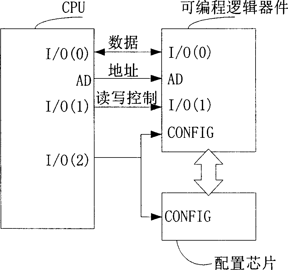
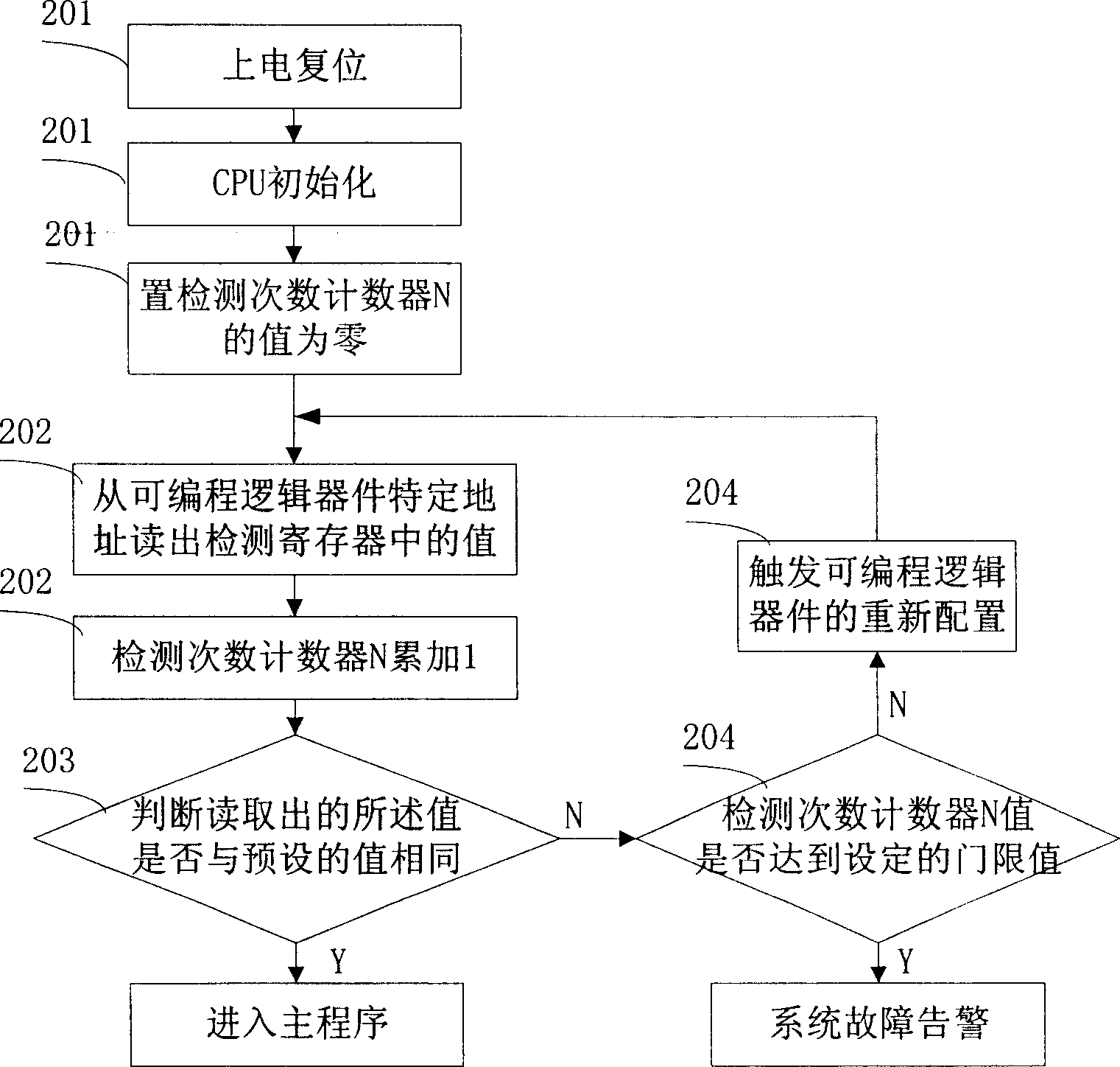
[0021] The design idea of ​​the present invention is: when designing the internal circuit of the programmable logic device, design a specified address as the specific register (referred to herein as the detection register), and give it a fixed value, when the programmable logic device is configured , the configuration chip transmits the information to be configured to the programmable logic device, including this specific register and its value. In the system initialization process, it is judged whether the CPU reads the value of the register correctly to determine whether the programmable logic device is configured correctly. If an error occurs during the configuration process, the configuration information will not be sent to the programmable logic device correctly, and the CPU will not be able to read the value of the register correctly. And when judging that the programmable logic device is not correctly configured, the CPU forcibly triggers the reconfiguration of the prog...


PUM


Abstract

The invention provides a programmable logic device collocation test method. When initializing the programmable logic device, the employed collocation information includes of allocating a specified address and storing a specified value. After system electrifying, this method includes: A. reading the value of the specified address; B. confirming the correction by comparing the reading and the specified value, if wrong, springing the initializing collocation and return to A. With this invention, the collocation correctness can be tested, and the test is not be disturbed by outside.

Description

technical field [0001] The invention relates to the technical field of detection, in particular to a detection method for programmable logic device configuration. Background technique [0002] FPGA (Field Programmable Gate Array, field programmable gate array) and CPLD (Complex P Programmable Logic Device, complex programmable logic device) are programmable logic devices, which are developed on the basis of PAL, GAL and other logic devices , Compared with the previous PAL, GAL and other logic devices, it has a larger scale and is suitable for timing and combination design. [0003] The description of the internal hardware connection relationship of the programmable logic device (referred to as the configuration file) can be stored in a storage unit such as a disk, ROM, PROM or EPROM. After the system is powered on, the configuration file can be written into the programmable logic device for automatic Programming, so when the programmable logic device and peripheral circuits...

Claims


Application Information

Patent Timeline
Patent Type & Authority Applications(China)
IPC IPC(8): G01R31/317G01R31/28
Inventor 高博刘飚
Owner DATANG MOBILE COMM EQUIP CO LTD
Learn More