
Power clipping circuit and power clipping method

A technology of limiting circuit and power, applied in electrical components, multiplexing communication, orthogonal multiplexing system, etc., can solve problems such as increasing circuit size, and achieve the effect of avoiding phase error

Inactive Publication Date: 2006-09-27
NEC CORP
View PDF3 Cites 6 Cited by
  • Summary
  • Abstract
  • Description
  • Claims
  • Application Information

AI Technical Summary

Problems solved by technology

Therefore, greatly increasing the size of the circuit

Method used


Image

  • Power clipping circuit and power clipping method
  • Power clipping circuit and power clipping method
  • Power clipping circuit and power clipping method

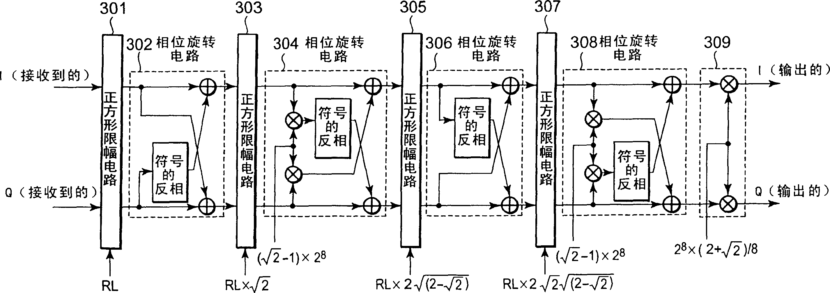
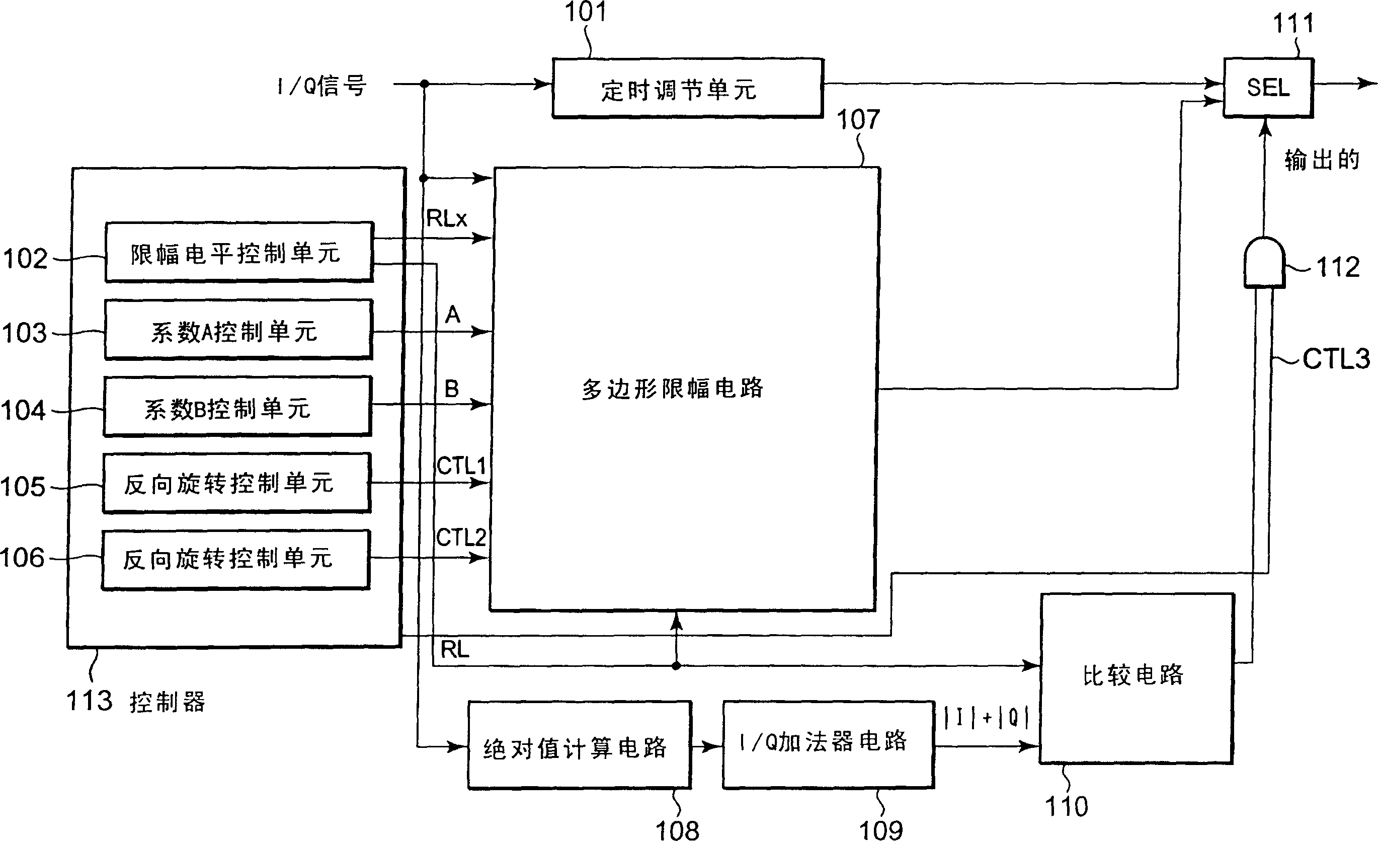
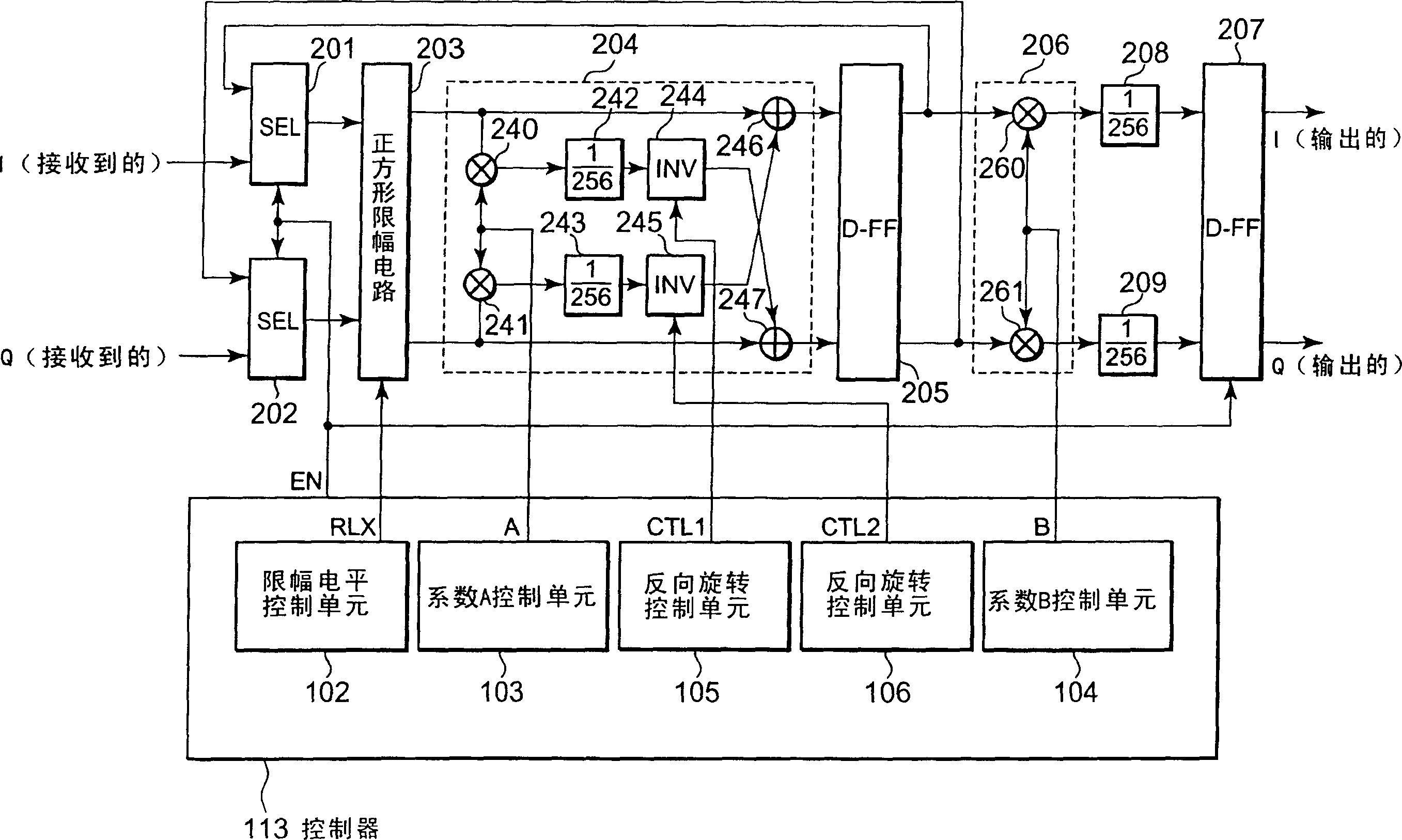
Examples


Embodiment Construction

[0023] Hereinafter, exemplary embodiments of the present invention will be described in detail with reference to the accompanying drawings. The exemplary embodiments are intended to help the understanding of the present invention, but are not intended to limit the scope of the present invention in any way.

[0024] In the case of the power clipping circuit according to the present invention, each of the I signal (common mode signal) and the Q signal (quadrature signal) of the baseband signal is input into the polygonal clipping circuit. The polygon clipping circuit is configured by a square clipping circuit, a phase rotation circuit and an amplitude scaling circuit. In the polygonal clipping circuit, the I and Q signals as received signals are input to the square clipping circuit and then processed by the square clipping process. The I and Q signals to which the square clipping process has been performed by the square clipping circuit are input to the phase rotation circuit. ...


PUM


Abstract

A power clipping circuit and method of the clipping circuit is provided. A power clipping circuit comprises, a selector which receives a baseband signal, and selects one of the baseband signal or a feed back signal, and outputs a selected signal, and a square clipping circuit which receives the selected signal, and limits an amplitude of the selected signal, and outputs a clipped signal, and a phase rotation circuit which receives the clipped signal, and rotates a phase of the clipped signal, and outputs a phase rotated signal to the selector as the feed back signal, and an amplitude scaling circuit which receives the phase rotated signal, and adjust the phase rotated signal to compensate an amplitude difference between the phase rotated signal and the clipped signal, and sends amplitude scaled signal, and a controlling circuit which controls the selector, the square clipping circuit, the phase rotation circuit and the amplitude scaling circuit.

Description

technical field [0001] The present invention relates to a power clipping circuit used in a baseband signal unit in a base station or the like using a W-CDMA (Wideband Code Division Multiple Access) radio communication system. Background technique [0002] In radio transmission devices (including mobile phones) of radio communication systems, power amplifiers used in linear digital modulation circuits with excellent linearity and high efficiency characteristics are generally considered to be beneficial for the amplitude of the transmitted signal of. However, using a power amplifier with excellent linearity for each transmitted signal also has disadvantages such as increases in circuit size, cost, and power consumption. Therefore, amplifiers generally used in this field are as follows. Although a power amplifier actually used can maintain linearity at a certain level, the power amplifier cannot maintain linearity beyond that level, and thus may output a non-linear signal. ...

Claims


Application Information

Patent Timeline
Patent Type & Authority Applications(China)
IPC IPC(8): H04B1/04H04B1/707H04J11/00
CPCH04B2201/70706H04B1/707H04L27/2624
Inventor 堀越修平
Owner NEC CORP
Learn More