
A hammering type button-stitching machine base with adjustment unit

An adjustment device, a technology of a button fixing machine, which is applied in the direction of mechanical equipment, belt fasteners, belts/chains/gears, etc., can solve problems such as troublesomeness, difficulty in use, and large size, and achieve firm button fastening and improved fastening buckle quality effect

Inactive Publication Date: 2006-09-27
SHANGHAI GORO CONVEYOR EQUIP CO LTD
View PDF0 Cites 0 Cited by
  • Summary
  • Abstract
  • Description
  • Claims
  • Application Information

AI Technical Summary

Problems solved by technology

As for the hydraulic binding machine, its structure is complicated and the volume is large, and every time a joint is ordered, it will be moved many times, which is both troublesome and difficult, with a large amount of labor, and the quality is not ideal; for the lever type binding machine, its cost is high , the price is expensive, the body is heavy, difficult to use, very inconvenient, and difficult to popularize and apply; for the hammer-type button-setting machine, it is more popular because of its small size and simple operation. The hammer presses the bow of the conveyor belt buckle, and makes it clamp the conveyor belt, and then hammers the punch to nail the buckle. Buckles and conveyor belts tend to move on the upper side of the base under the guide die, affecting the quality of the fasteners

Method used


Image

  • A hammering type button-stitching machine base with adjustment unit
  • A hammering type button-stitching machine base with adjustment unit

Examples


Embodiment Construction

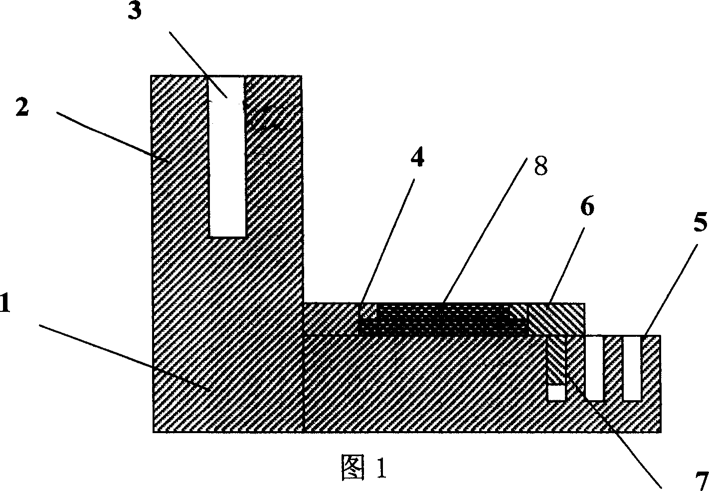
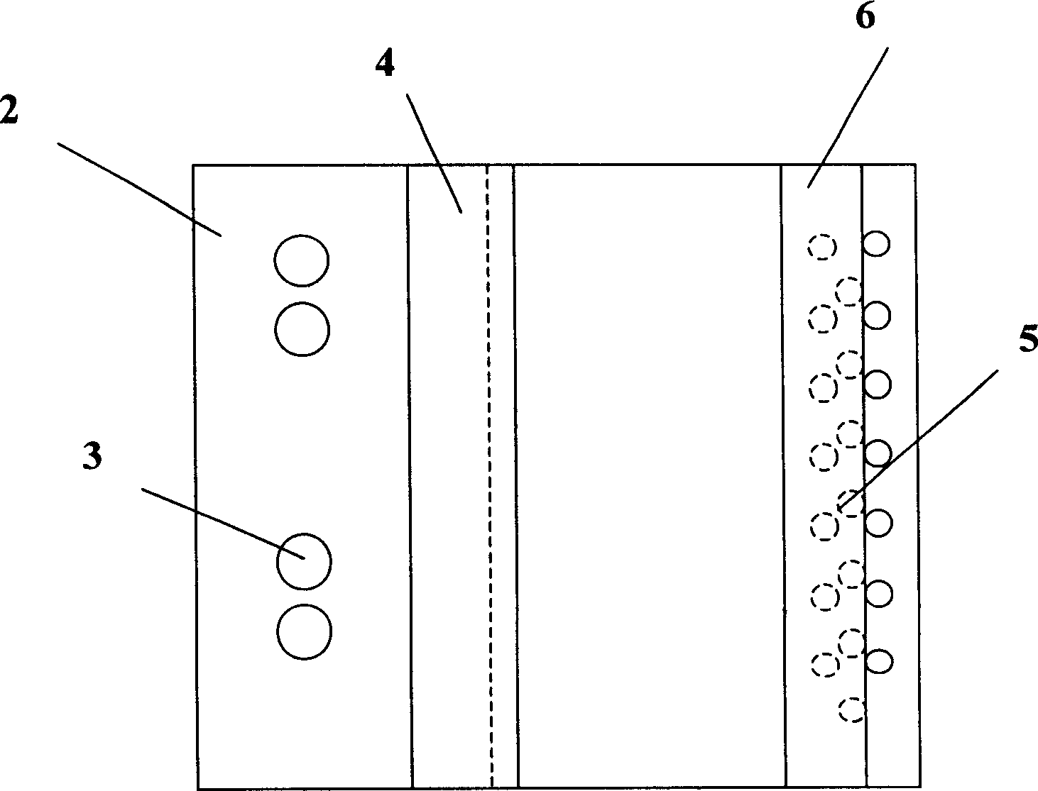
[0012] Figure 1 and figure 2 As shown, the present invention has a hammer type fastener base with an adjustment device, which is composed of a base 1, the rear side of the base 1 protrudes upwards to form a boss 2, and the boss 2 A mold guide pin hole 3 is provided on the top, and a hinge joint is provided on the front part of the boss 2, wherein a step 4 is provided on the upper side of the base 1, and a step 4 is provided on the upper side of the base 1. At least two rows of positioning holes 5 are arranged in the center, and the alignment direction of any one row of positioning holes 5 is parallel to the step 4, and any adjacent two rows of positioning holes 5 are provided with intervals. The positioning holes 5 are at least composed of two or more holes, the positioning holes 5 are perpendicular to the upper side of the base 1, and the upper side of the base 1 is provided with a Positioning rod 6, described positioning rod 6 is arranged at least at the opening end of a ro...


PUM


Abstract

The invention relates to a hammer buckling base with an adjuster formed by a base. wherein, the upper side surface of base has a step and at least two row of positioning holes, whose arranged direction is parallel with the step; there are space between the positioning holes; the upper side surface of base has one positioning rod which at least on the open end of one row of positioning holes, while the lower side surface of positioning rod is vertically mounted with a projecting cylinder inside he positioning hole. First, arranging the feeding belt buckle on the upper side surface of base, the lower part of said buckle is arranged into the groove formed by the step and the positioning rod; the hinge head of buckle is meshed with the hinge head of base to fix the buckle, and via arranging the positioning rod into different positioning holes, the distance between the rod and step can be changed to meet the demand.

Description

Technical field: [0001] The invention relates to a binding tool, in particular to a binding tool for conveyor belt buckles, in particular to a hammering type binding machine, in particular to a hammering type binding machine base with an adjusting device. Background technique: [0002] In the prior art, the binding of the conveyor belt buckle generally adopts a hydraulic buckle binding machine, a lever type buckle binding machine or a hammer type buckle binding machine, and multiple conveyor belt buckles are bound at the belt joint each time. As for the hydraulic binding machine, its structure is complicated and the volume is large, and every time a joint is ordered, it will be moved many times, which is both troublesome and difficult, with a large amount of labor, and the quality is not ideal; for the lever type binding machine, its cost is high , the price is expensive, the body is heavy, difficult to use, very inconvenient, and difficult to popularize and apply; for the h...

Claims


Application Information

Patent Timeline
Patent Type & Authority Applications(China)
IPC IPC(8): F16G3/16
Inventor 任英广陆俭
Owner SHANGHAI GORO CONVEYOR EQUIP CO LTD
Learn More