Switch

A switch and device body technology, which is applied in the direction of switch status indication, circuit breaker parts, etc., can solve problems such as complex structure and achieve the effect of simple structure

Active Publication Date: 2006-09-20
MATSUSHITA ELECTRIC WORKS LTD
View PDF1 Cites 2 Cited by
  • Summary
  • Abstract
  • Description
  • Claims
  • Application Information

AI Technical Summary

Problems solved by technology

[0006] In the latter case, in the method in which the handle drives the drive member through the link, a separate member for displaying the welding state of the contacts is required, and there is a problem that the structure becomes complicated.

Method used


Image

  • Switch
  • Switch
  • Switch

Examples


Embodiment Construction

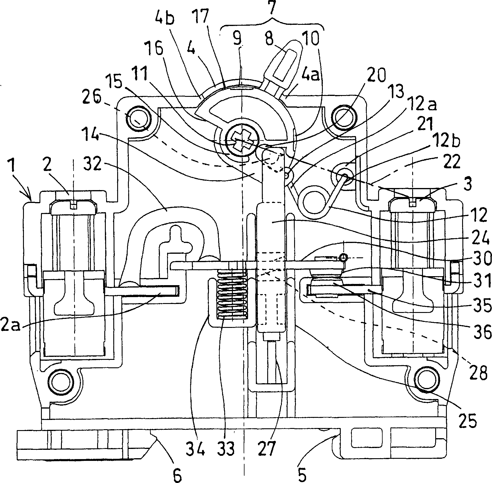
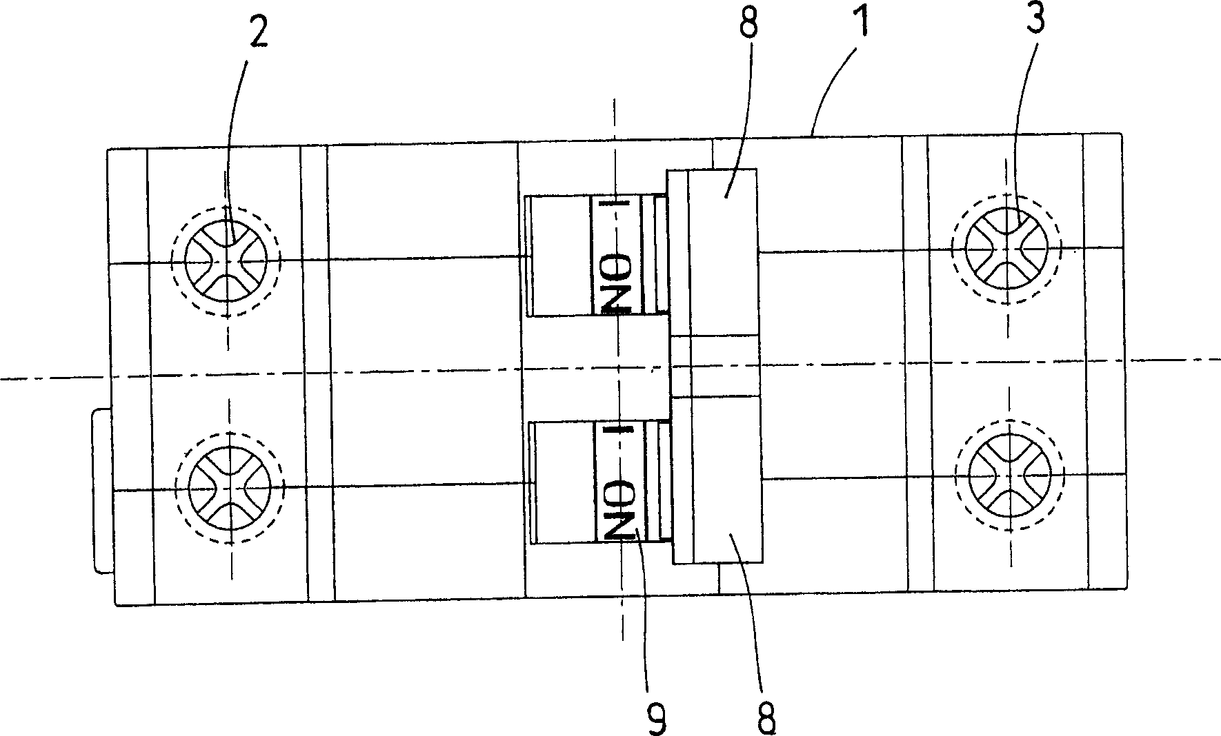
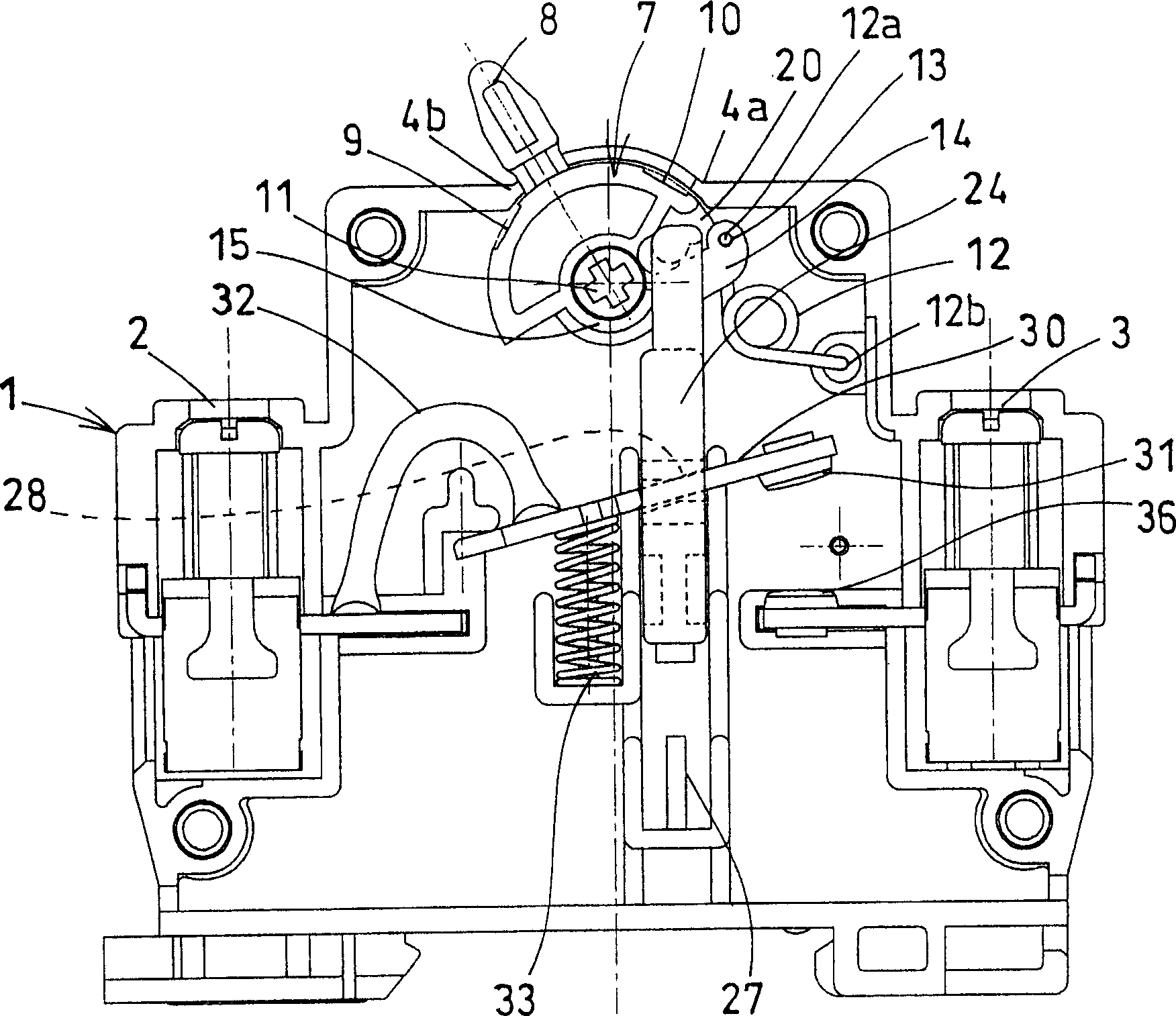
[0018] pass Figure 1 to Figure 3 A switcher according to one embodiment of the present invention will be described. The switch has a body 1 , a handle 7 , a torsion coil spring 12 as a reversing spring, a driving part 24 , a movable contact block 30 , and a fixed contact 36 .

[0019] The body 1 is provided with input and output terminals 2 and 3 on both sides, and a handle hole 4 is formed on the upper surface. On the lower surface of the body 1, fixed claws 5 and movable claws 6 for rail installation are provided facing each other.

[0020] The handle 7 is roughly semi-cylindrical, and a bearing portion 15 is formed at the center of its flat portion 16. The bearing portion 15 is pivotally supported by a shaft 11 supported by the inner side of the handle hole 4 on the top of the body 1 . The axis 11 is at right angles to the direction connecting the input and output terminals 2 and 3 . An operating portion 8 protruding from the handle hole 4 is provided substantially in t...


PUM


Abstract

The invention discloses a switcher (1), which comprises handle hole (4). Wherein, the handle (7) has an operate part (8) projected from the handle hole (4), a switch display part (9) near the operate part (8), a clamp hole (13) and nearby hook part (20), which via torsion screw spring (12) is held at the open or close position; the driving element (24) has the projection (26) clamped with the hook part (20), to be supported by the device (1) to move oscillating, and be driven by the switching operation of operate part (8); the movable contact block (30) is held by the driving element (24) with a movable connect point (31) opposite to the fixed connect point (36). The inventive switcher has simple structure, while the handle display part will not be contained into device even when rotating the handle to the close position when melting the connect point.

Description

technical field [0001] The present invention relates to a switch device for switching and driving contacts intervening in an electric circuit through the switch operation of a handle. Background technique [0002] When an abnormal current flows through the contact, the circuit breaker that forcibly opens the contact (for example, refer to Patent Document 1) is: the handle is linked with the driving part through the link (link) and the action block, and the movable contact is driven by the driving part The block makes the movable contact separate from the fixed contact, and when the abnormal current flows, the abnormal current detection device detects the characteristic device, releases the locked state of the action block and the characteristic device, and makes the movable contact from the fixed contact through the action of the spring. Forced disconnection. In addition, the handle is provided with an open display part that is exposed outside the circuit breaker in the ope...

Claims


Application Information

Patent Timeline
IPC IPC(8): H01H73/12
Inventor 北村孝
Owner MATSUSHITA ELECTRIC WORKS LTD
Why Eureka
Try Eureka