Gearbox drive unit

A technology of drive unit and transmission device, applied in the direction of electromechanical devices, electrical components, electric components, etc., can solve problems such as redesign, and achieve the effect of simplified manufacturing

Inactive Publication Date: 2006-09-06
ROBERT BOSCH GMBH
View PDF1 Cites 0 Cited by
  • Summary
  • Abstract
  • Description
  • Claims
  • Application Information

AI Technical Summary

Problems solved by technology

The known transmission drive unit has the disadvantage that the housing part of the transmission drive unit needs to be redesigned for the changed screw connection type (Anschraubbild) due to the change of the fixing position
In particular, transmission drive units that are modularly combined are often only suitable for a certain purpose

Method used


Image

  • Gearbox drive unit
  • Gearbox drive unit
  • Gearbox drive unit

Examples


Embodiment Construction

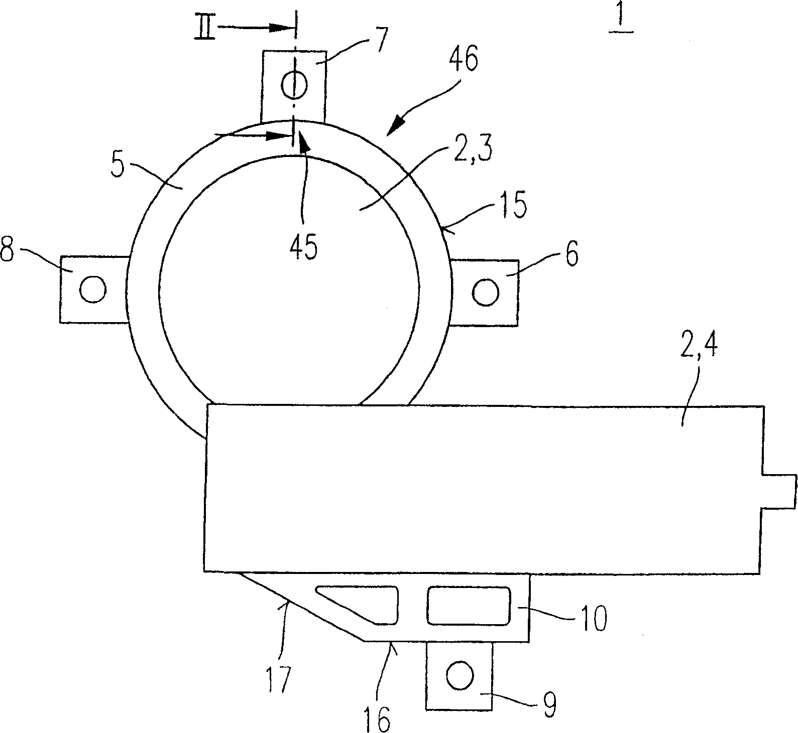
[0016] figure 1 A first embodiment of a transmission drive unit 1 of the invention is shown. The transmission drive unit 1 is particularly suitable for adjusting moving parts in a motor vehicle, for example for adjusting windows or sliding sunroofs. However, the transmission drive unit 1 according to the invention is also suitable for other applications.

[0017] The transmission drive unit 1 comprises a housing part 2 which is assembled from a transmission housing part 3 and a drive housing part 4 . The transmission housing part 3 of the housing part 2 has an annular segment 5 interrupted in the region of the drive housing 4 of the housing part 2 . The transmission housing part 3 is provided with fastening covers 6 , 7 , 8 , and a fastening cover 9 is fastened to the drive housing part 4 via a fastening element 10 which is part of the housing part 2 .

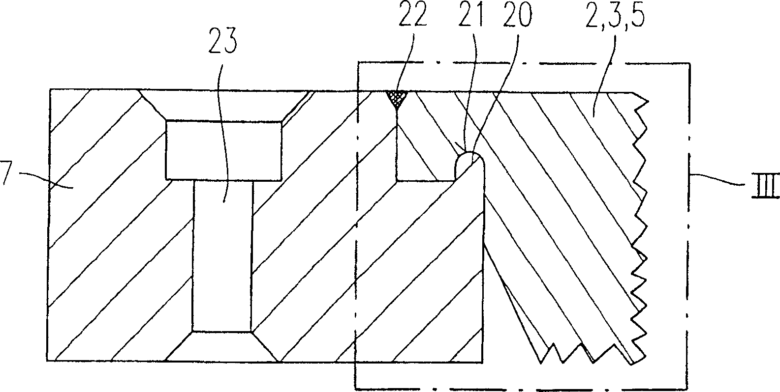
[0018] The fastening bells 6 , 7 , 8 can be moved along the circumference 15 of the ring segment 5 before being fastened ...


PUM


Abstract

A transmission drive unit (1), especially suitable for adjusting movable parts in a motor vehicle, comprising at least one housing part (2) and at least one fixed cover (6, 7, 8, 9). Wherein, the fixing covers (6, 7, 8, 9) are used for fixing the transmission drive unit (1). The housing part (2) has a first connection point (45) and at least one second connection point (46) to which a fixed cover (6, 7, 8, 9) can be mounted. According to the given threaded connection form related to the fixing of the transmission drive unit (1), the fixed cover (6, 7, 8, 9) is connected to the housing at the first connection position (45) or the second connection position (46) Parts (2) are joined together.

Description

[0001] The invention relates to a transmission drive unit of the type described in the independent claim. Background technique [0002] DE 100 19 512 A1 discloses a transmission drive unit of the type described in the independent claims. [0003] The transmission drive unit disclosed in this patent document has a housing part on which several fastening covers are arranged. In addition, the known transmission drive unit drive also has a drive which is of the electromechanical type and which is particularly suitable for use as a window regulator motor or a sunroof motor in motor vehicles. In this case the housing part is of modular construction, ie different gear housings and electronics housings can be combined into different motor housings via the housing of the gear drive unit. The housing part of the transmission drive unit is fastened, for example, by screwing the housing part onto a fastening cover on the body part or the seat structure. From this, the spatial arrangemen...

Claims


Application Information

Patent Timeline
Patent Type & Authority Applications(China)
IPC IPC(8): E05F15/16H02K5/26H02K5/00H02K7/116
CPCH02K5/00H02K7/1166E05F15/1692E05Y2900/55E05F15/697Y10T74/2186B60J1/17E05F15/665
Inventor R·兰佩特W·豪塞克R·库尔茨曼M·格德克P·弗勒利希D·比约卡西克
Owner ROBERT BOSCH GMBH
Why Eureka
Try Eureka