


Quick Research
Generate reliable direction feasibility study reports for your R&D in just a few steps.

Technical Q&A
Discover and master advanced knowledge NOW. Basics, ideas, possibilities, all at once.

Find Solutions
As an expert in R&D theories, this can generate solutions to your technical problems instantly.

Evaluate Feasibility
Analyze your overall solution with one click, know your potential R&D risks in advance.

Monitor Landscape
Get weekly tech updates, stay abreast of the latest tech innovations and key insights.
Intarsia shuttle box
A shuttle box and box body technology is applied in textile and papermaking, weft knitting, knitting and other directions, which can solve the problems of the shaking of the yarn feeder fixing plate and the unstable positioning of the yarn feeder, so as to reduce the manufacturing cost, simplify the structure and simplify the machinery. The effect of the transmission locking device
- Summary
- Abstract
- Description
- Claims
- Application Information
AI Technical Summary
Problems solved by technology
Method used
Image

Examples
Embodiment Construction
[0023] The present invention will be further described below in conjunction with the accompanying drawings and embodiments.
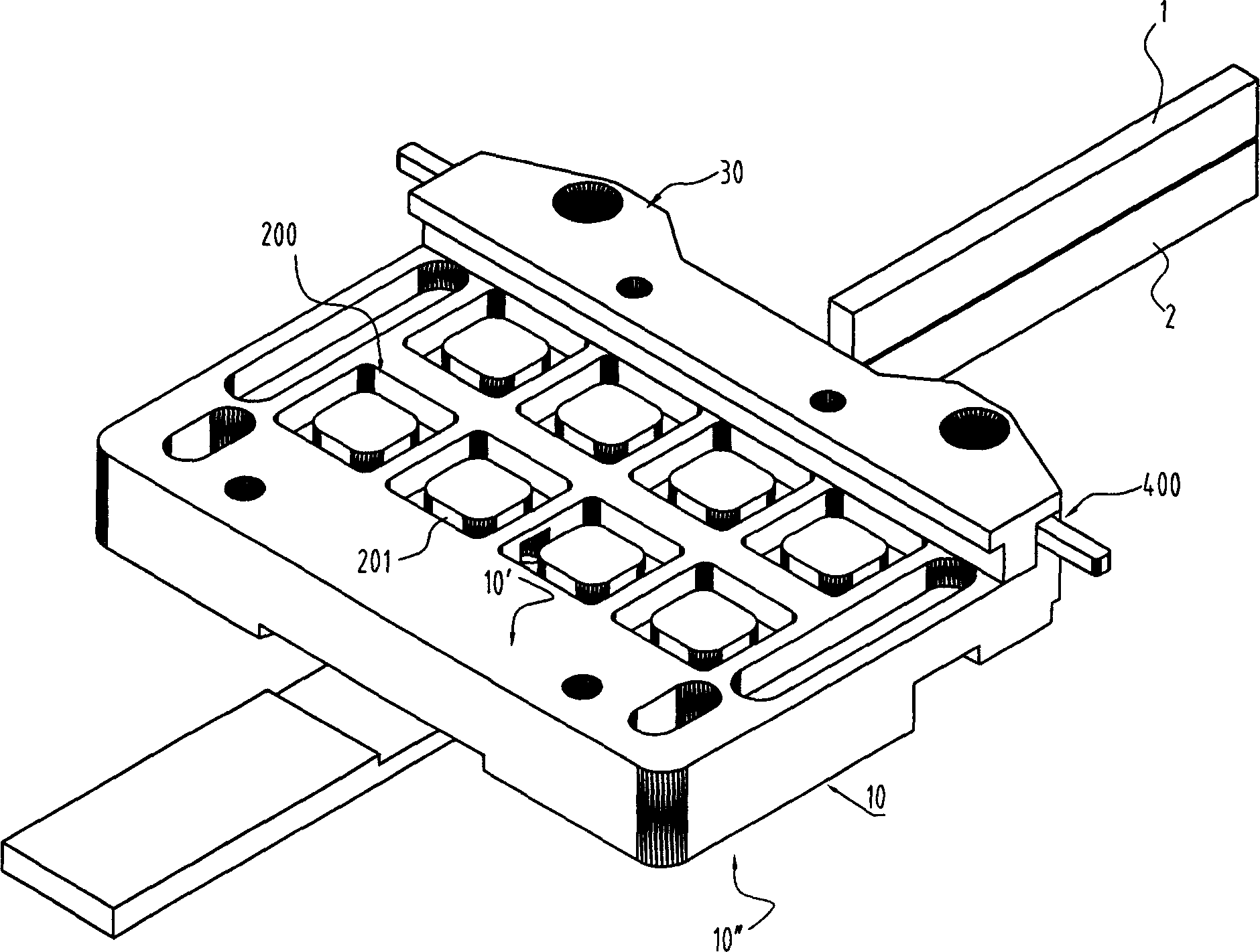
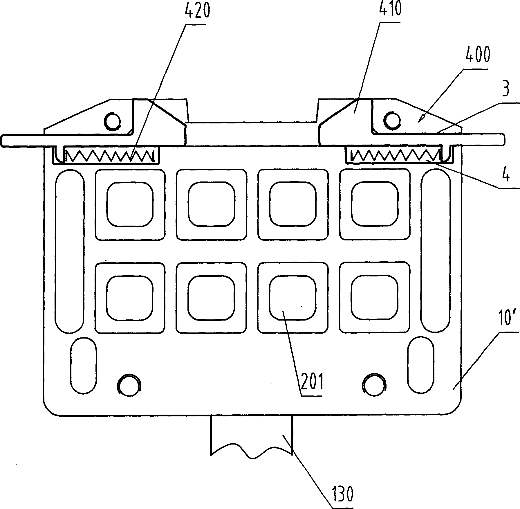
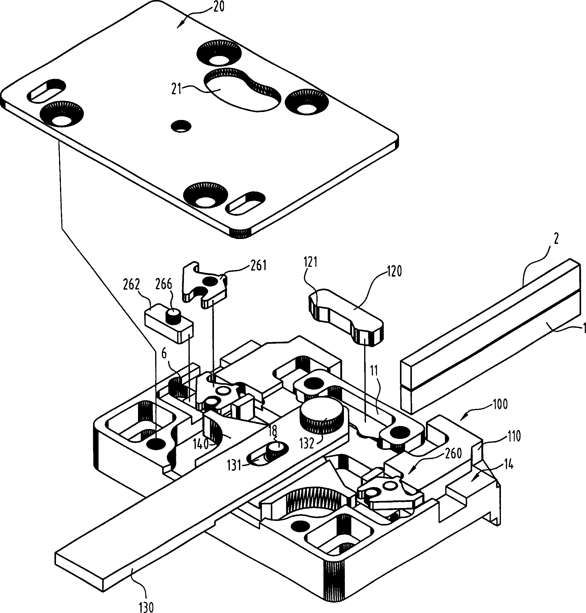
[0024] The intarsia shuttle box of the present invention is composed of a box body 10 , an outer cover plate 20 , an inner cover plate 30 , an anti-collision device 400 , a magnetic resistance positioning device 200 and a yarn feeder moving device 100 .
[0025] Wherein the anti-collision device 400 and the magnetic resistance positioning device 200 are placed on the inner side of the box body 10', please refer to figure 1 and figure 2 . The magnetic resistance positioning device 200 is composed of 8 pieces of magnetic steel 201, which are fixed on the inner side 10' of the box body. The box body 10 is adsorbed on the shuttle bar 40 through the magnetic steel 201, and can be moved along the shuttle bar 40 under the push of the tongue 2. The guide positioning surface 41 slides, so that the intarsia shuttle box moves, please refer to Figure 7 . The ...
PUM
| Property | Measurement | Unit |
|---|---|---|
| Inclination | aaaaa | aaaaa |
Abstract
Description
Claims
Application Information
 - R&D Engineer
- R&D Manager
- IP Professional
- Industry Leading Data Capabilities
- Powerful AI technology
- Patent DNA Extraction
Browse by: Latest US Patents, China's latest patents, Technical Efficacy Thesaurus, Application Domain, Technology Topic, Popular Technical Reports.
© 2024 PatSnap. All rights reserved.Legal|Privacy policy|Modern Slavery Act Transparency Statement|Sitemap|About US| Contact US: help@patsnap.com