
Glass cutting table

A glass cutting, cutting table technology, applied in glass cutting devices, glass manufacturing equipment, lighting and heating equipment, etc.

Inactive Publication Date: 2006-08-16
彼得·利泽克
View PDF2 Cites 5 Cited by
  • Summary
  • Abstract
  • Description
  • Claims
  • Application Information

AI Technical Summary

Problems solved by technology

EP 0 673 890 B uses an arm that can be swiveled upwards from the support plate for holding the glass sheet, in order to avoid the disadvantages of a glass cutting table with a support plate formed as an overturning table, but it must be tolerated for ejecting (supporting) the glass. Defects of swivel arms

Method used


Image

  • Glass cutting table
  • Glass cutting table
  • Glass cutting table

Examples


Embodiment Construction

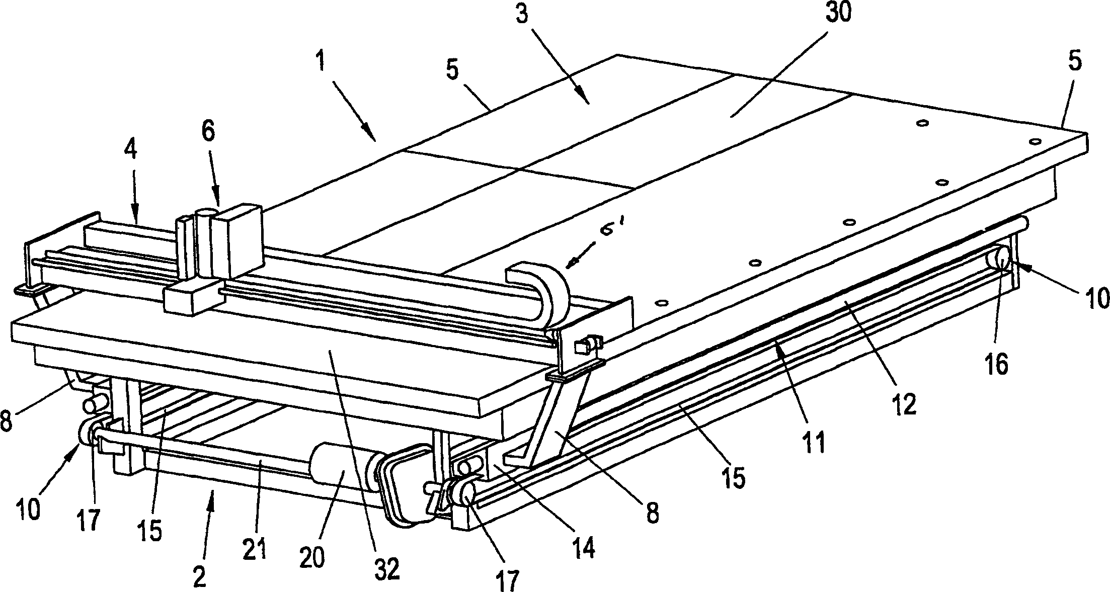
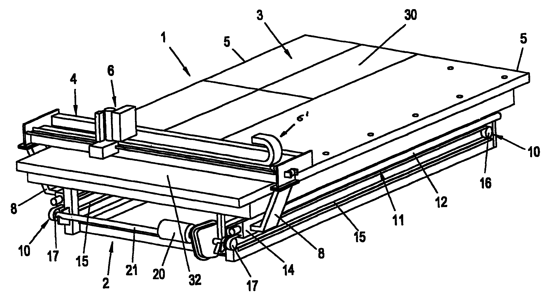
[0019] one in figure 1 The glass cutting table 1 shown in an oblique view in and 2 has a base 2 standing on the ground via feet not shown. The base 2 supports a flat plate 3 (platen), which serves as a support for the glass panes (ribbon-shaped dimensions) to be separated. The flat plate 3 can be equipped with a conveying mechanism not shown for moving and positioning the glass sheets to be separated before and after cutting. Furthermore, the plate 3 has a felt pad, and there is the possibility of constituting the plate 3 as an air-cushioned plate, in which case there are patterned air outlet holes in the plate 3 for delivery to these The compressed air in the opening thus forms an air cushion between the flat plate 3 forming the carrier and a glass plate, which reduces the friction between the glass plate and the carrier 3 .

[0020] The plate 3 is mostly rectangular. A cutting bridge 4 is provided parallel to the shorter side of the plate 3 as a support. The cutting brid...


PUM


Abstract

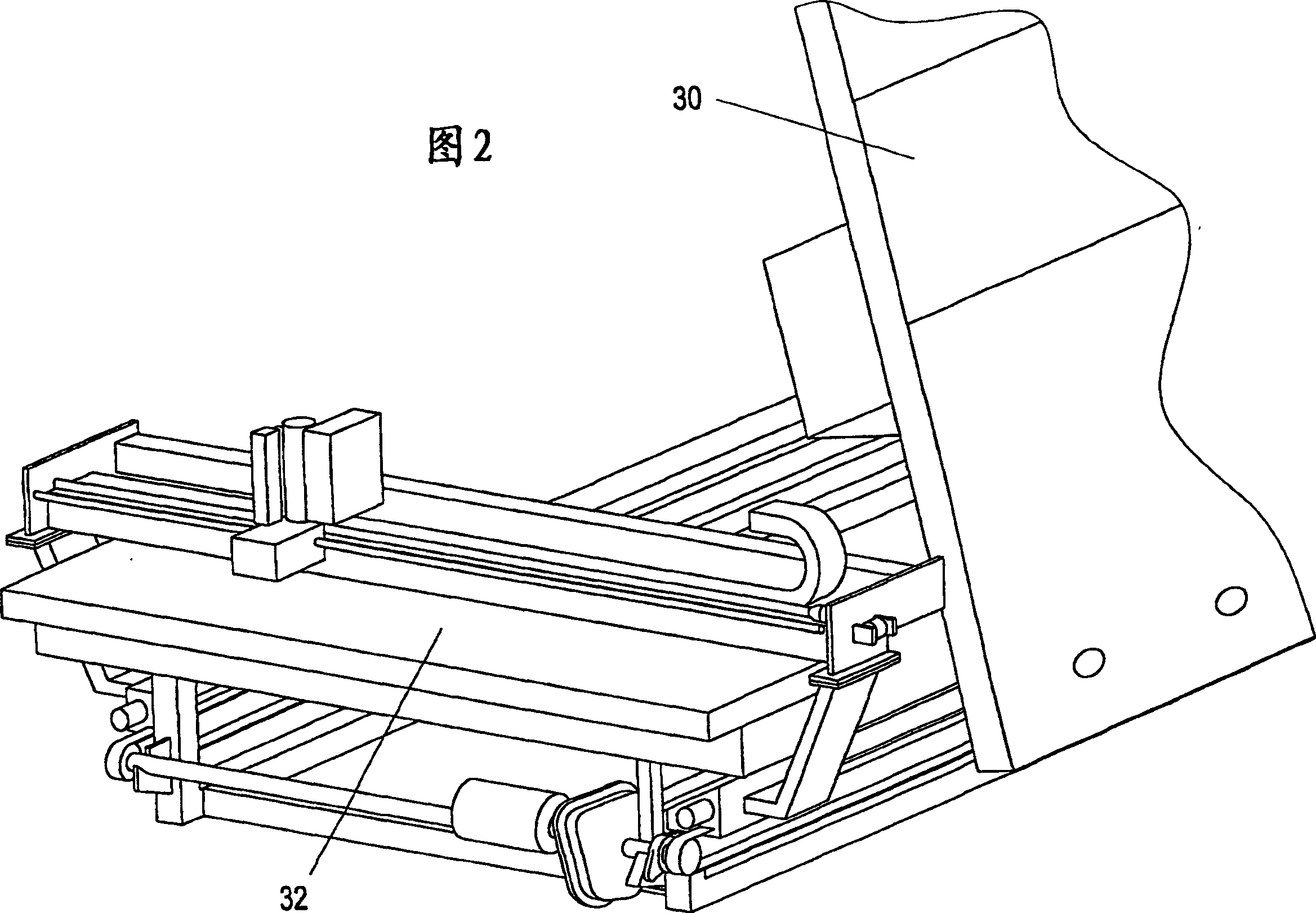
Disclosed is a glass cutting table (1) comprising a support in the form of a plate (3) for the glass plate that is to be divided, a cutting bridge (4) which can be displaced along the support and on which a cutting head (6) encompassing a cutting tool is disposed in an adjustable manner. The driving and directing unit (10) for the cutting bridge (4) is placed at a distance below the plate (3) forming the support of the glass cutting table (1) and is fastened to the base frame (2) of the glass cutting table (1) independently of the plate (3). In addition, the directing and driving unit (10), which is composed of guide bars (12) for the cutting bridge (4) and a toothed wheel-toothed belt drive (15, 16, 17) for moving the cutting bridge (4) relative to the outer contour of the plate (3) of the glass cutting table (1), especially the longitudinal edges (5) of the plate (3), is offset in an inward direction such that the support of the glass cutting table (1) is easy to access while the directing and driving unit (10) does not risk being dirtied or damaged by glass splinters. Moreover, when a sectional plate (3) is used, the tiltable part (30) thereof can be tilted independently of the directing and driving unit (10) so as to receive glass plates that are to be divided.

Description

technical field [0001] The invention relates to a glass cutting table with the features of claim 1, which has a support for the glass panes to be separated, has a cutting bridge which can be moved along the support and has a movable arrangement on the cutting bridge. cutting head. The cutting head carries a knife, such as a cutting wheel, for scoring the glass pane along the dividing contour. Background technique [0002] Such glass cutting tables are known. [0003] In a known glass cutting table, the cutting bridge is guided on a guide rod, for example a round rod, which is mounted near a support designed as a table plate for the glass panes to be separated. A drive for moving the cutting bridge is also fitted in the region of the bearing for the glass panes to be parted. [0004] Drives are known for moving (moving) the cutting bridge along the support, which have a toothed rack mounted in the area of ​​the support of the glass pane to be separated and a pinion driven ...

Claims


Application Information

Patent Timeline
Patent Type & Authority Applications(China)
IPC IPC(8): C03B33/03C03B33/023B65G49/06C03B33/027
CPCC03B33/03Y10T83/0333C03B33/027Y10T83/7755B65G49/067
Inventor 彼得·利泽克
Owner 彼得·利泽克
Learn More