
Combined puncturing wire clip

A puncture wire clip and a combined technology, applied in the field of combined puncture wire clips, can solve problems such as complicated operation, and achieve the effects of convenient use, simple structure and low cost

Inactive Publication Date: 2006-07-26
舒红彪 +1
View PDF0 Cites 13 Cited by
  • Summary
  • Abstract
  • Description
  • Claims
  • Application Information

AI Technical Summary

Problems solved by technology

When fast equipotential bonding is performed on multiple cables at the same time, multiple piercing clamps are required, and the operation is more complicated

Method used


Image

  • Combined puncturing wire clip
  • Combined puncturing wire clip

Examples


Embodiment Construction

[0009] Specific embodiments of the present invention will be described in detail below in conjunction with technical solutions and accompanying drawings.

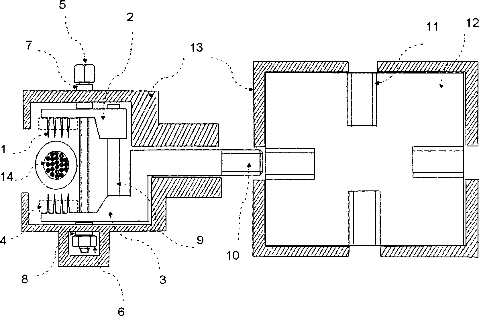
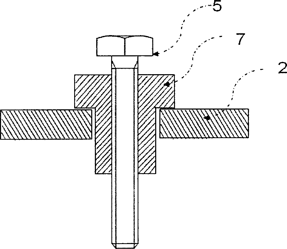
[0010] The puncture tool is composed of a steel upper occlusal body 2, a lower occlusal body 3 and a stainless steel thorn block group 1 with an insulating sealing gasket 4 on the thorn block group. A steel column 9 and a conductor 10 are welded on the lower occlusal body. One end of the upper occlusal body is worn on the upright, and can move up and down through the upright. The torque bolt 5 cooperates with the nut 6 to complete the occlusal operation of the upper and lower occlusal bodies. The engineering plastic insulating pressure pads 7 and 8 insulate the torque bolts. The structure of the insulating pressure pad is as follows: figure 2 shown. The thread at the tail end of the conductor can be screwed into the threaded hole 11 on the common connector 12, so that the conductor and the common connector can be connect...


PUM


Abstract

This invention relates to one transparent cable connector in electrical connection tool technique field and in detail to one combined transparent clamper. This invention is mainly composed of several connection branches formed by public connectors and the connection branch joint and relative conductor and the conductor and public connector are connected through screw. The cable pass process is fulfilled by the cable joint force screw bolt tighten tool.

Description

technical field [0001] The invention belongs to the technical field of electrical connection fittings, and relates to a piercing cable connector, in particular to a combined piercing clip. Background technique [0002] Insulated cables are an important part of power systems. In order to realize the fast and safe connection of insulated cables, various cable connectors have been invented, among which the insulation piercing clamp is a kind of fast connection fitting for cables that is widely used at present. Existing insulation piercing clamps are mainly composed of two sets of piercing tools, torque bolt tightening tools, and insulating gaskets arranged in the same insulating housing. The piercing connector with this structure can only complete the connection between two cables at a time. Equipotential bonding. When fast equipotential bonding is performed on multiple cables at the same time, multiple piercing clamps are required, and the operation is relatively complicated...

Claims


Application Information

Patent Timeline
Patent Type & Authority Applications(China)
IPC IPC(8): H01R4/24
Inventor 舒红彪王晓臣
Owner 舒红彪
Learn More