Electromagnetic drive device

A technology of electromagnetic drive and drive components, applied in the direction of electromechanical devices, electromagnets, valve devices, etc., can solve the problem that the flat structure cannot be realized, and achieve loose and imprecise effects

Inactive Publication Date: 2010-08-11
FESTO AG & CO KG
View PDF5 Cites 2 Cited by
  • Summary
  • Abstract
  • Description
  • Claims
  • Application Information

AI Technical Summary

Problems solved by technology

With known arrangements, a flat structural approach cannot be achieved

Method used


Image

  • Electromagnetic drive device
  • Electromagnetic drive device
  • Electromagnetic drive device

Examples


Embodiment Construction

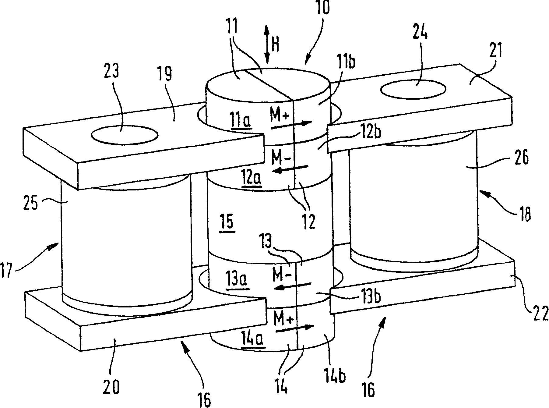
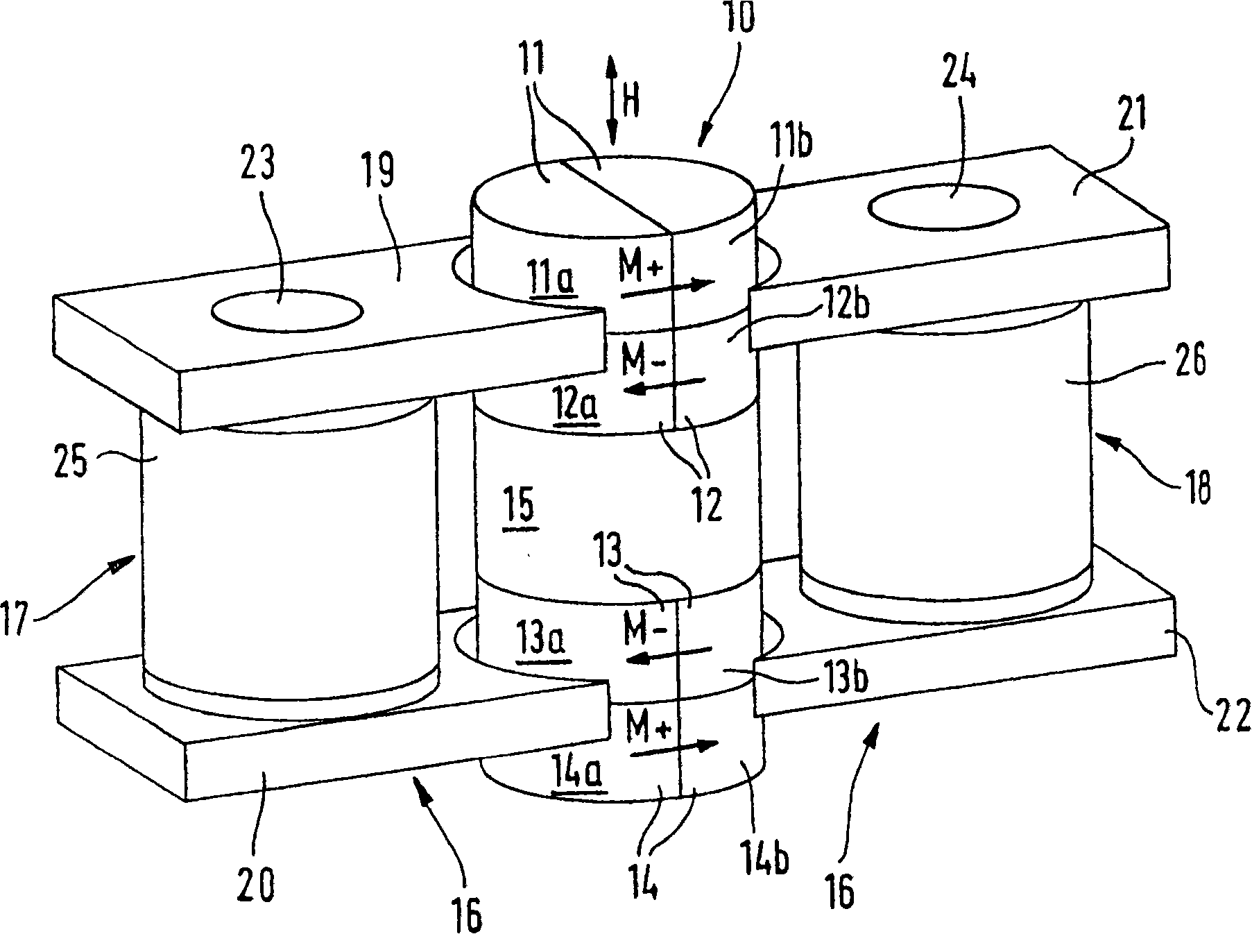
[0016] In the first embodiment shown in FIG. 1 , the cylindrical drive element 10 comprises four disc-shaped magnet parts 11 to 14 which are magnetized transversely to the direction of travel H, on the one hand arranged one behind the other in the direction of travel The magnet parts 11 and 12 and on the other hand also the magnet parts 13 and 14 arranged one behind the other in the direction of travel are magnetized in opposite directions, indicated by the magnetic field arrows M+ and M−. Adjacent magnet parts 11 and 12 are spaced apart from likewise adjacent magnet parts 13 and 14 by a cylindrical intermediate section 15 consisting of a non-magnetizable material, for example plastic. However, it can also consist of a magnetizable material, or it can be omitted if the dimensions of the magnet parts 11 to 14 correspond.

[0017] The magnet parts 11 to 14 are constituted by two half-discs 11a to 14a and 11b to 14b respectively in order to be able to achieve the desired magnetiz...


PUM


Abstract

The invention relates to an electromagnetic drive device, comprising a drive part (10), which has a circular or oval cross-section, can move in a to-and-fro manner in the stroke direction (H), and which has a permanent magnet arrangement that is magnetized transversal to the stroke direction (H). Said permanent magnet arrangement has at least one pair of oppositely magnetized magnet parts (11-14)that are placed one behind the other in the stroke direction, and is situated in the interspace of a yoke arrangement (16) having pole pieces (19-22) that, in the magnetizing direction, are provided on opposite sides of the drive part (10). The yoke arrangement (16) has two pairs of pole pieces (19, 21 and 20, 22), which delimit the interspace and which are connected to one another via two yoke areas (23, 24) extending essentially parallel to the stroke direction (H). At least one of the yoke areas (23, 24) is surrounded by a coil (25, 26) that can be flown through in order to effect a stroke. A pair of oppositely magnetized magnet parts (11, 12 and 13, 14) of the permanent magnet arrangement is assigned to each pair of pole pieces (19, 21 and 20, 22). This makes it possible to easily obtain a very slim design.

Description

technical field [0001] The invention relates to an electromagnetic drive device comprising a reciprocating drive part in the direction of travel and having a circular or elliptical cross-section, said drive part having a magnetized drive part transverse to the direction of travel. A permanent magnet arrangement having at least one pair of oppositely magnetized magnet parts arranged sequentially in the direction of travel and arranged in a gap of a yoke having a direction of magnetization of the drive part Pole shoe on opposite side. Background technique [0002] The electromagnetic drive as disclosed in DE 19 900 762 C2 has only two pole pieces arranged on opposite sides of the drive part, which are respectively surrounded in an annular manner by an energizable coil, so that the axial direction of the coil is aligned with the drive part magnet. The magnetization directions of the parts are the same. In a preferred embodiment, the drive member is flat and plate-like. [00...

Claims


Application Information

Patent Timeline
Patent Type & Authority Patents(China)
IPC IPC(8): H01F7/122F16K31/08H01F7/16H02K33/16H01F7/08
CPCH01F7/081H01F7/122F16K31/082H01F7/1646H02K33/16
Inventor J·格尔哈茨R·施温策尔
Owner FESTO AG & CO KG
Why Eureka
Try Eureka