High power light source regulating apparatus
A light source adjustment, high-power technology, applied in optics, optical components, instruments, etc., can solve the problems of reduced optical efficiency and device performance, and achieve the effect of wide adjustment range, strong practicability, and reliable mechanical stability.
- Summary
- Abstract
- Description
- Claims
- Application Information
AI Technical Summary
Problems solved by technology
Method used
Image
Examples
Embodiment 1
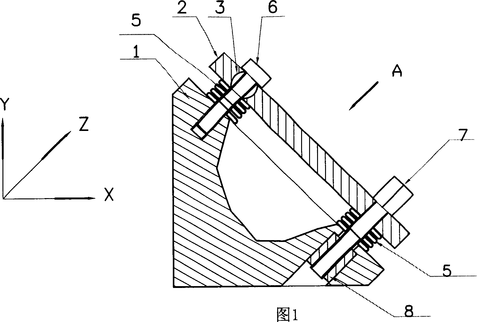
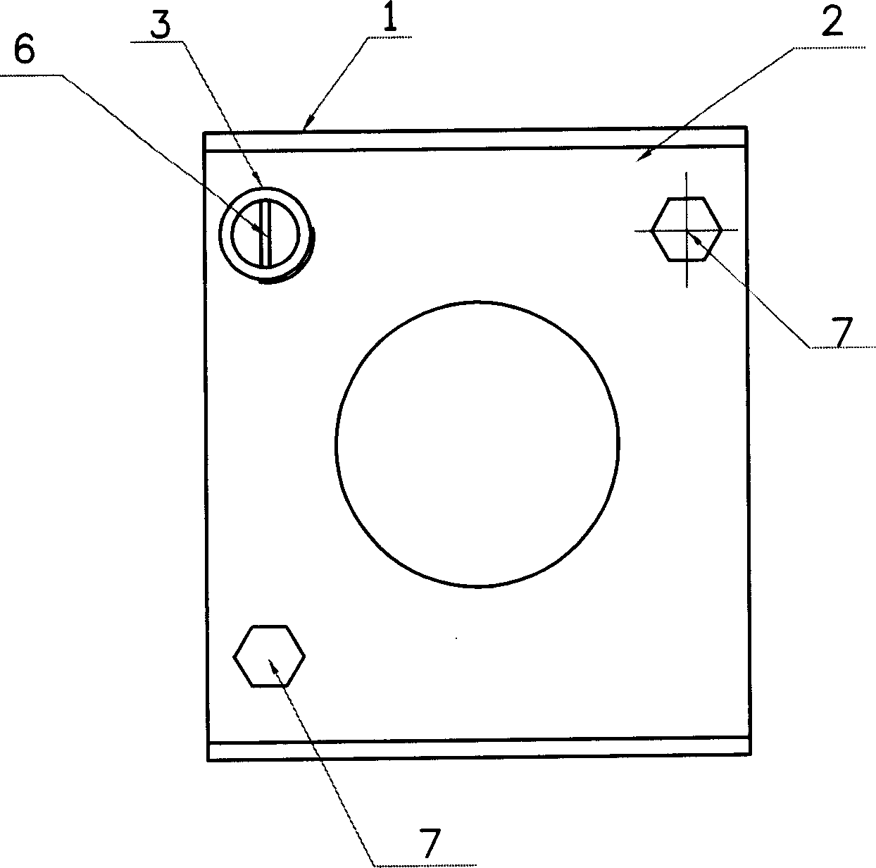
[0028] Embodiment 1: as shown in Figure 1, figure 2 As shown, a high-power light source adjustment frame includes a metal support body 1, a metal adjustment plate 2, a ball head adjustment assembly and two screw adjustment assemblies, and a ball head is placed between the metal support body 1 and the metal adjustment plate 2. The adjustment assembly is connected with two screw adjustment assemblies. The metal support 1 is provided with threaded holes 10 and 11 for installing the ball head adjustment assembly and the screw adjustment assembly. The metal adjustment plate 2 is provided with a concave hemispherical hole 12 for installing the ball head 3 And the mounting hole 14 for installing the adjusting screw 7, the two screw adjusting assemblies are respectively installed on the diagonal position of the metal support body 1 and the metal adjusting plate 2, the advantage of this arrangement is that when adjusting any adjusting screw 7, the metal The adjustment plate 2 will move...
Embodiment 2
[0029] Embodiment 2: as Figure 8 The shown high-power light source adjustment device has the same basic structure as that of Embodiment 1, except that the spring plate 5 of the ball head adjustment assembly should be set between the fixing screw 6 and the metal adjustment plate 2 . The effect of adopting this structure is that it can overcome the defect that the reference point of the metal adjustment plate 2 drifts during the adjustment process caused by the spring piece 5 being arranged between the metal support body 1 and the metal adjustment plate 2 in the first embodiment. Because when adjusting the adjustment screw 7 of a certain adjustment assembly, as the metal adjustment plate 2 moves on the spherical surface of the ball head part 3, the force on each point on the spring leaf 5 is uneven, and the original reference point of the metal adjustment plate 2 will be changed. A certain amount of drift occurs, making it difficult to precisely adjust the angle of the metal ad...
Embodiment 3
[0030] Embodiment 3: as Figure 9 The shown high-power light source adjustment device has the same basic structure as that of Embodiment 2, except that: the metal support body 1 has a through hole 15, and the hemispherical head piece 4 has a cylindrical rear portion 16. There is a threaded hole 17 in the middle of the hemispherical head piece 4 and its cylindrical rear part 16. The cylindrical rear part 16 passes through the through hole 15, and the fixing screw 6 and the threaded hole 17 cooperate with each other to fix and connect the metal adjustment plate 2 and the ball head adjustment. Assemblies and the metal support body 1, the axial direction of the through hole 15 is perpendicular to the working surface of the metal support body 1. The effect of adopting this structure is: the gravity component of the metal adjustment plate 2 originally carried by the fixing screw 6 It is changed to be carried by the cylindrical rear part 16 of the hemispherical head piece 4, which im...
PUM
 Abstract
Description
Claims
Application Information
 - Generate Ideas
- Intellectual Property
- Life Sciences
- Materials
- Tech Scout
- Unparalleled Data Quality
- Higher Quality Content
- 60% Fewer Hallucinations
Browse by: Latest US Patents, China's latest patents, Technical Efficacy Thesaurus, Application Domain, Technology Topic, Popular Technical Reports.
© 2025 PatSnap. All rights reserved.Legal|Privacy policy|Modern Slavery Act Transparency Statement|Sitemap|About US| Contact US: help@patsnap.com


