Anti-oil leakage device of top bend needle mechanism

A technology for preventing oil leakage and bending needles, which is used in safety devices, engine lubrication, engine sealing, etc., can solve the problems of poor lubricating oil scraping effect, reduced oil leakage prevention function, and pollution of sewing machine frame, etc. Reliable effect of scraping action

Inactive Publication Date: 2011-06-15
YAMATO SEWING MASCH MFG CO LTD
View PDF2 Cites 3 Cited by
  • Summary
  • Abstract
  • Description
  • Claims
  • Application Information

AI Technical Summary

Problems solved by technology

However, no matter how small and suitable the gap is set, as the sewing machine is used, there will be friction between the two, and the gap will become larger with this friction, and the scraping effect of excess lubricating oil will gradually deteriorate. The amount of splashing upwards, and then flowing downwards along the outer peripheral surface of the upper looper base, contaminating the sewing machine frame, etc., increases, and the specified oil leakage prevention function gradually decreases.
[0005] In addition, in the above-mentioned conventional device, the scraped excess lubricating oil is temporarily accumulated in the upper part of the cylindrical upper looper guide body (in Japanese Patent Laid-Open No. 9-66184, it is along the upper half of the upper looper guide body). The upper end in the oil groove formed by bending the peripheral surface in an arc shape; in Japanese Patent Application Laid-Open No. 2004-187940, it is formed in the opening around the upper end of the through hole of the upper looper guide body), and the gravity and negative pressure are used to , or by the forced suction generated by the pump (oil discharge), so dust such as yarn scraps and cloth scraps scattered from above the upper looper guide body are mixed into the remaining lubricating oil accumulated, and the mixed dust clogs the oil discharge As a result, the amount of excess lubricating oil accumulated on the upper part of the cylindrical upper looper guide gradually increases, and the prescribed oil leakage prevention function rapidly declines prematurely.

Method used


Image

  • Anti-oil leakage device of top bend needle mechanism
  • Anti-oil leakage device of top bend needle mechanism
  • Anti-oil leakage device of top bend needle mechanism

Examples


Embodiment Construction

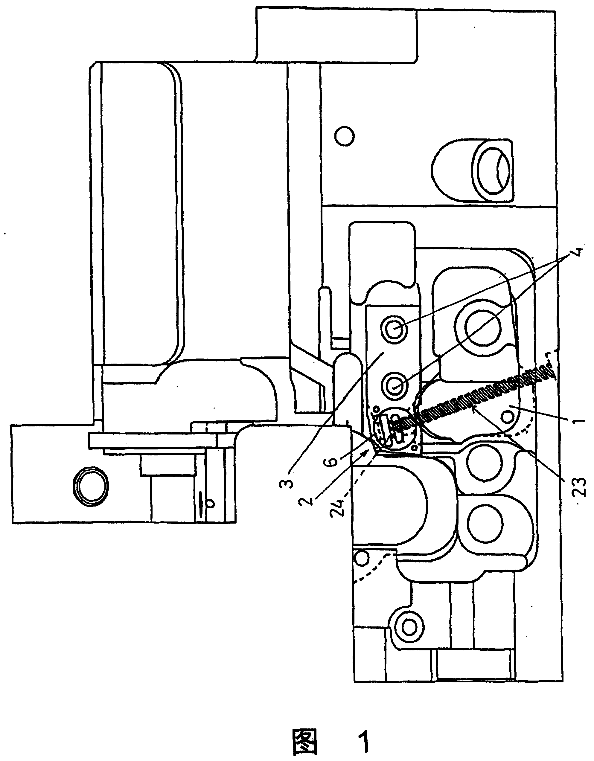
[0023] figure 1 It is a front view of the whole sewing machine frame 1 in the overlock sewing machine incorporating the oil leakage prevention device of the upper looper mechanism according to the present invention, with the machine cover installed in front of it removed, the upper looper Mechanism 2 is located in front of the sewing machine frame 1 .

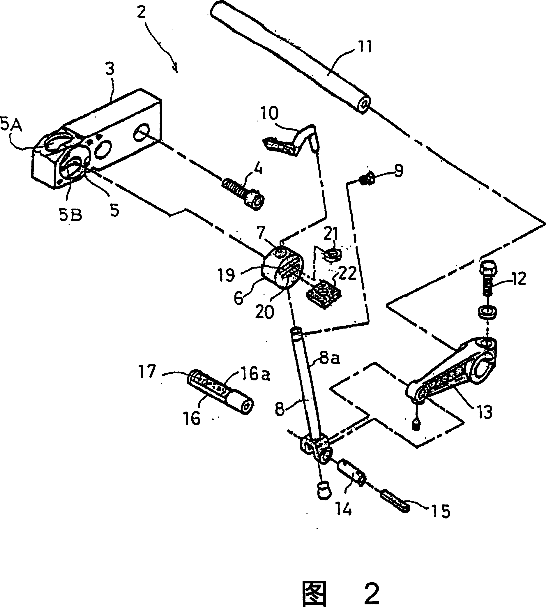
[0024] figure 2 It is an exploded perspective view of the upper looper mechanism 2, image 3 It is an assembly perspective view of the upper looper mechanism 2, Figure 4 It is a front view of the upper looper mechanism 2. In these figures, 3 is the upper looper guide part fixed on the front of the sewing machine frame 1 by fastening screws 4, and the circular hole 5 along the cloth conveying direction has holes facing the upper looper guide part 3 up and down. The state of the openings 5A, 5B on the upper surface and the lower surface is formed at the tip end portion of the upper looper guide member 3 . In the circular h...


PUM


Abstract

To make a scraping off function for a surplus lubricant to be certainly and excellently exerted, to enable the long and stable maintenance of a prescribed oil leakage prevention capacity by avoiding the mixing of dust in the surplus lubricant and to enable the reuse of the surplus lubricant for the maintenance of the lubrication capacity for a vertical motion of an upper looper table. Two upper penetrating slot holes perpendicularly intersecting a penetration hole for the upper loop table to slidingly go up and down are bored in a cylindrical upper looper guiding body which is engaged and supported in a circular hole bored in an upper looper guiding member fixed to a sewing machine frame to be rotatable around the center of the circle, and an oil seal ring with an elastic lip which elastically touches by sliding a peripheral surface of the upper looper table and scrapes off the surplus portion of the lubricant attached to the peripheral surface and an oil absorbent ring which can absorb and keep the scraped surplus lubricant are respectively engaged with the upper penetration long hole and the lower penetration slot hole.

Description

technical field [0001] The present invention relates to an oil leakage preventing device for an upper looper mechanism in an overlock sewing machine, and in particular to preventing the remaining lubricating oil being The reciprocating lifting of the upper looper seat leaks and splashes to the surroundings, especially the upper part of the upper looper guide part to pollute the thread and cloth, etc. The oil leakage prevention device of the upper looper mechanism, more specifically relates to the oil leakage prevention device with the following devices The oil leakage prevention device of the upper looper mechanism: the upper looper guide part fixed on the sewing machine frame; the cylinder freely rotatable around the center of the circle in the circular hole formed in the upper looper guide part Shaped upper looper guide body; freely slide through the hole formed in the radial direction of the upper looper guide body, and fix the upper looper seat on the upper end of the loop...

Claims


Application Information

Patent Timeline
Patent Type & Authority Patents(China)
IPC IPC(8): D05B71/02
CPCD05B57/00D05B71/02F16J15/50F16N31/00F16N2210/32F16N2260/00
Inventor 金川靖南
Owner YAMATO SEWING MASCH MFG CO LTD
Why Eureka
Try Eureka