
Image forming apparatus and processinh caddy

An image and charging device technology, which is applied in the direction of the electric recording process using the charge pattern, the equipment and the instrument of the electric recording process using the charge pattern, and can solve the problem of not considering the light attenuation characteristics, the change of the toner image density, and the inability to Forming images etc.

Active Publication Date: 2006-05-24
RICOH KK
View PDF1 Cites 3 Cited by
  • Summary
  • Abstract
  • Description
  • Claims
  • Application Information

AI Technical Summary

Problems solved by technology

However, in this case, the following problems will occur: it is necessary to form the above-mentioned latent image pattern on the surface of the photoreceptor, and the time from forming the latent image pattern on the surface of the photoreceptor to the end of setting the exposure conditions corresponding to the film thickness t cannot be form an image
The calculation method described in Patent Document 1 obtains the exposure amount based on the light attenuation characteristic corresponding to the film thickness, but since the fluctuation of the light attenuation characteristic relative to the above-mentioned uniform charging potential Vd is not taken into account, the toning on the photoreceptor occurs. The problem that the density of the agent image changes

Method used


Image

  • Image forming apparatus and processinh caddy
  • Image forming apparatus and processinh caddy
  • Image forming apparatus and processinh caddy

Examples


Embodiment Construction

[0051] Hereinafter, embodiments of the present invention will be described in detail with reference to the drawings.

[0052] An example of an electrophotographic printer (hereinafter abbreviated as "printer") will be specifically described as an image forming apparatus.

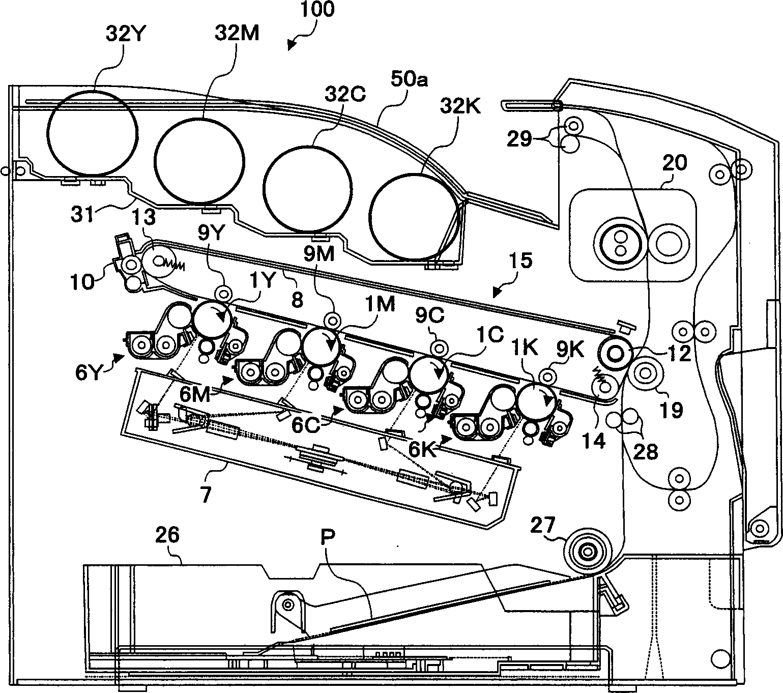
[0053] First, the basic configuration of this printer will be described. figure 1 It is a diagram showing the schematic configuration of this printer. In the figure, the printer 100 is provided with four process cartridges 6Y, 6M, 6C, and 6K, and the process cartridges 6Y, 6M, 6C, and 6K are used to generate yellow, magenta, cyan, and black (hereinafter abbreviated as "Y, M, C, K") toner images. In these process cartridges, toners of different colors, ie, Y, M, C, and K toners are used as image forming substances, but the surroundings thereof have the same configuration, and are exchanged when the service life is reached.

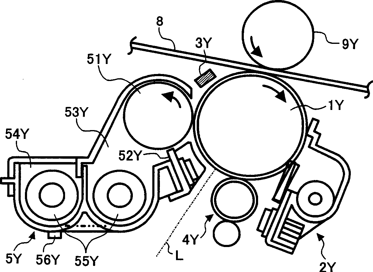
[0054] Taking the process cartridge 6Y for generating Y toner images as an example...


PUM


Abstract

The present invention relates to image forming devices such as copiers, facsimile machines, and printers, and process cartridges. The film thickness of the image carrier is predicted from the number of revolutions of the image carrier, and the optimum exposure conditions are calculated based on the predicted film thickness of the image carrier and the target uniform charging potential Vd. This provides an image in which optimal exposure conditions corresponding to both the uniform charging potential of the image carrier and the film thickness of the image carrier can be obtained, and an image can be formed from the start of setting the optimal exposure condition to the end of the setting. Forming device and process cartridge.

Description

technical field [0001] The present invention relates to image forming devices such as copiers, facsimile machines, and printers, and process cartridges. Background technique [0002] Generally, in an image forming apparatus, a charging roller, a transfer roller, a developer, a cleaning blade, a cleaning brush, etc. are provided, and these are in contact with the surface of an image carrier. As the image carrier rotates, its surface is gradually abraded. As a result, there arises a problem that the film thickness of the charge transport layer forming the surface layer of the photoreceptor gradually becomes thinner, and the exposure sensitivity of the photoreceptor fluctuates. If the exposure sensitivity changes, the light attenuation characteristic in which the uniform charge potential Vd decays to the post-exposure potential V1 changes, and the toner density of the halftone on the photoreceptor changes. [0003] For the above problems, the following methods can be consider...

Claims


Application Information

Patent Timeline
Patent Type & Authority Applications(China)
IPC IPC(8): G03G15/00G03G15/043G03G15/06
CPCG03G15/75G03G2215/0119G03G2221/183G03G15/553G03G15/556G03G15/04
Inventor 村上和歌子桑原延雄三瓶敦史木村祥之长岛弘恭细川浩
Owner RICOH KK
Learn More