
Rotary power machine

A power machine and rotating device technology, applied in the direction of engine components, machines/engines, mechanical equipment, etc., can solve problems such as environmental pollution and limited resource storage, and achieve the effect of simple structure and unrestricted use environment

Inactive Publication Date: 2006-05-17
任文华
View PDF0 Cites 0 Cited by
  • Summary
  • Abstract
  • Description
  • Claims
  • Application Information

AI Technical Summary

Problems solved by technology

After all, the storage of coal, oil and other resources on the earth is limited, and the massive use of these resources has brought serious pollution to the environment
Although the use of water energy, wind energy, and solar energy has no pollution, it is subject to restrictions such as climate and region

Method used


Image

  • Rotary power machine
  • Rotary power machine
  • Rotary power machine

Examples


Embodiment Construction

[0023] Describe below in conjunction with embodiment and accompanying drawing:

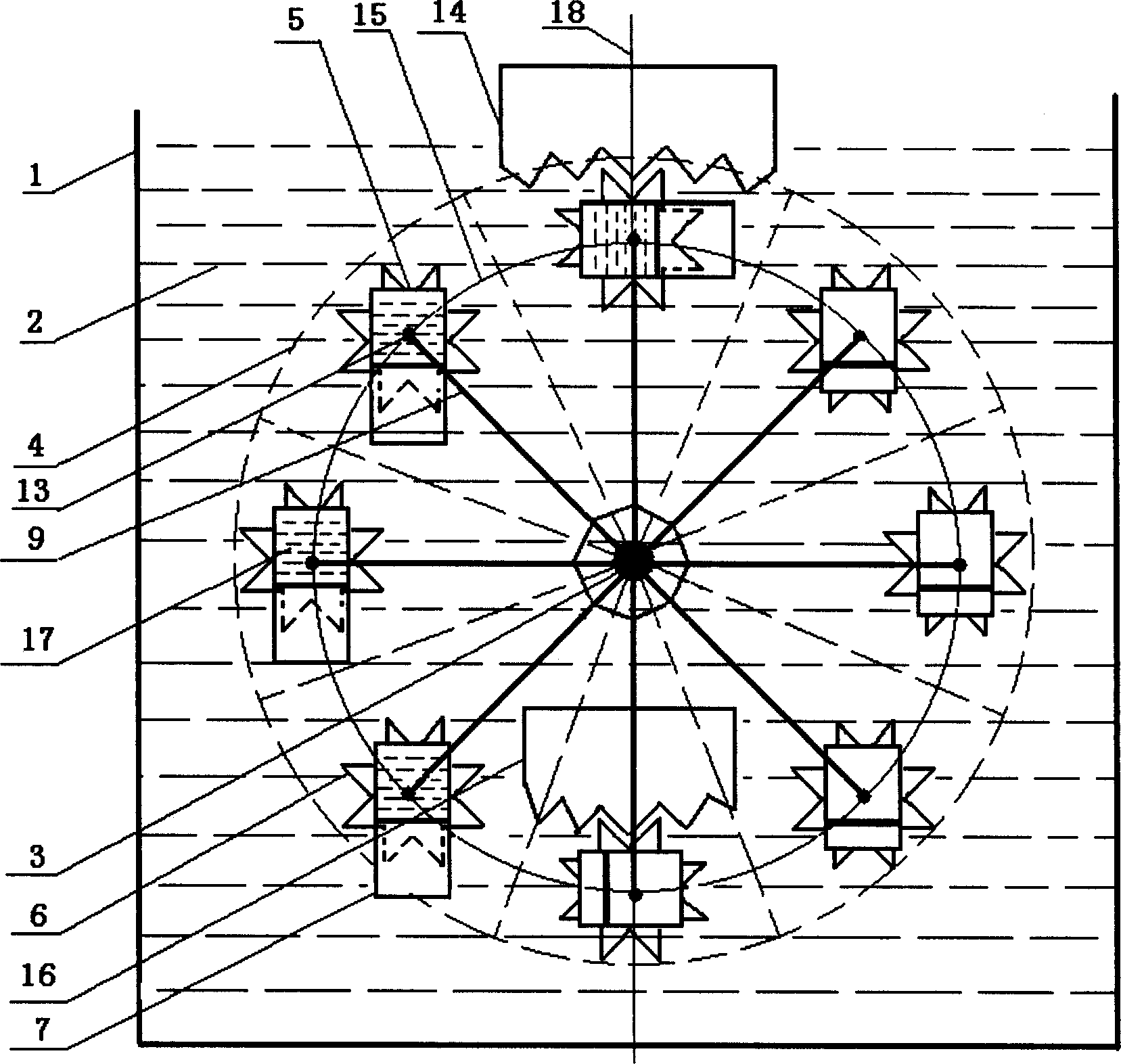
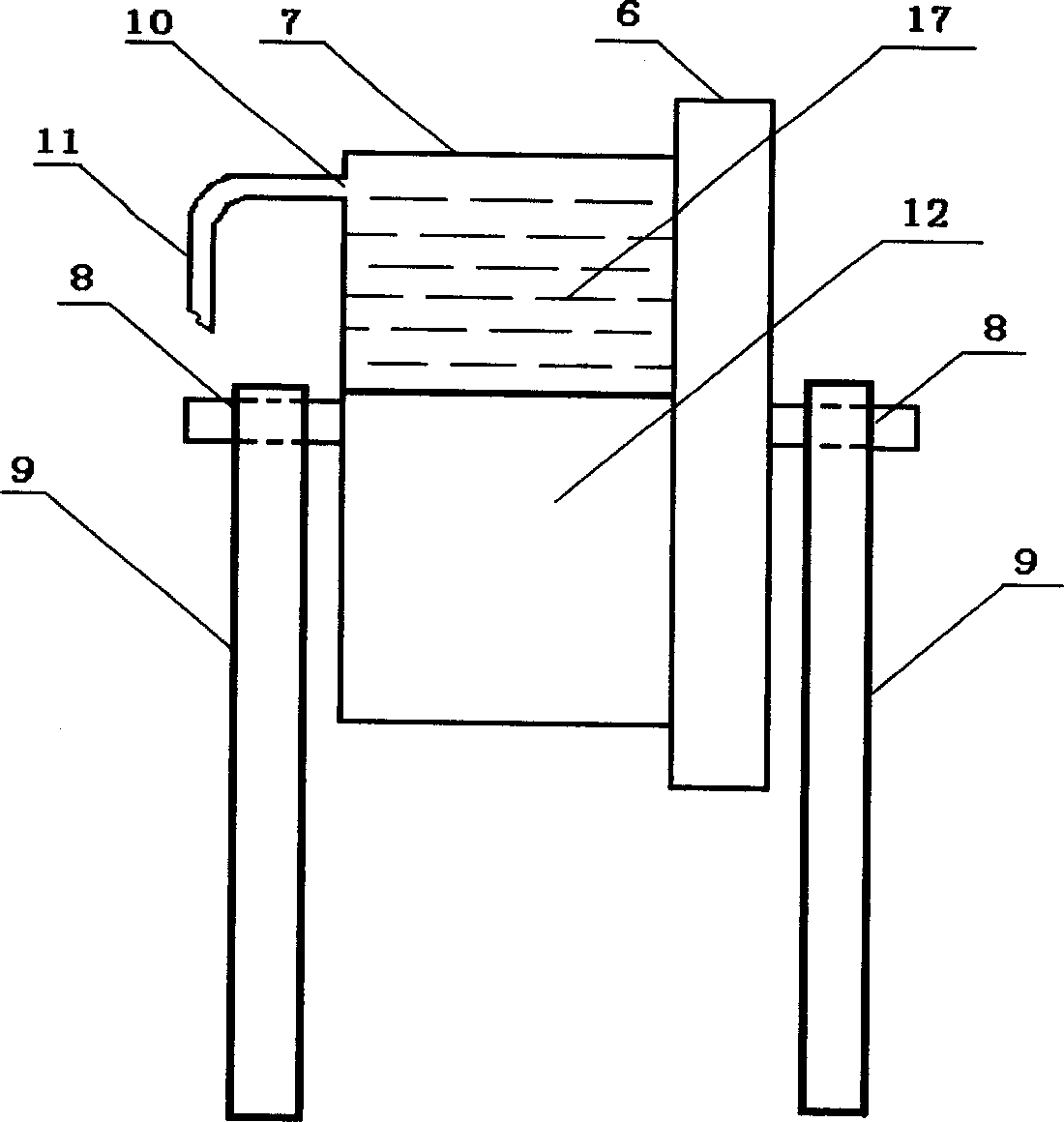
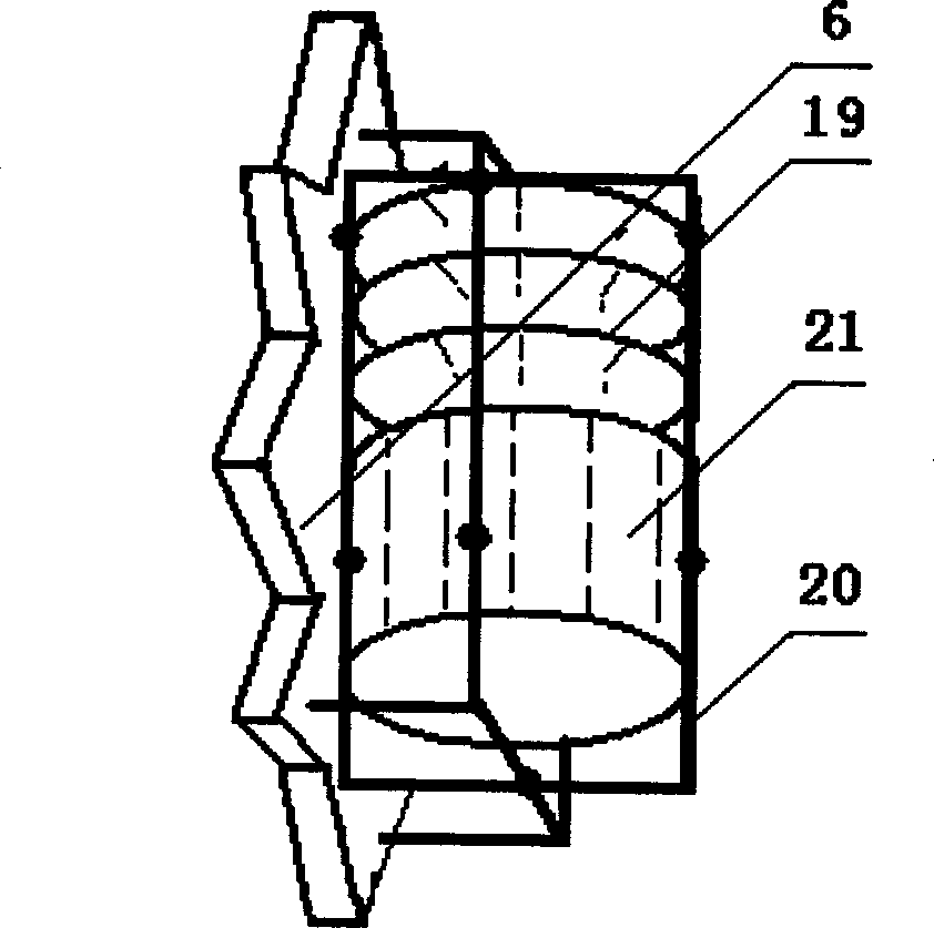
[0024] In each drawing: 1 is a liquid storage container, 2 is a liquid, 3 is a rotating shaft, 4 is a small fan-shaped area, 5 is a gear-container combination device, 6 is a gear, 7 is a container, 8 is a bearing, and 9 is a support rod , 10 is the fluid inlet and outlet, 11 is the conduit, 12 is the sliding body, 13 is the support point, 14 is the wall tooth, 15 is the circumference, 16 is the wall tooth, 17 is the working fluid, 18 is the vertical symmetry line, 19 is the telescopic Formula buoy, 20 is a support, and 21 is a cylindrical sliding body.

[0025] see figure 1 The rotary power machine of the present invention comprises a liquid storage container 1, a liquid 2, a vertically placed rotating shaft 3, a pair of wall teeth placed at the vertical upper end and the vertical lower end of the circumference 15, a set The running wheel of 8 gear-container combination devices 5 has been provid...


PUM


Abstract

The present invention relates to a rotation power machine. It is mainly formed from liquid storage container, liquid and rotation device. It is characterized by that the described rotation device includes a horizontally-placed rotating shaft, a pair of wall teeth and a rotating wheel equipped with several gear-container combined devices. Under the action of gravity and rising force said device can be continuously rotated, and can be used as prime motor.

Description

technical field [0001] The invention relates to a mechanical power device. Background technique [0002] The mechanical power device can output power externally and perform work externally, and has a wide range of uses. At present, human beings are facing the living situation of energy shortage and environmental pollution. After all, the storage of coal, oil and other resources on the earth is limited, and the extensive use of these resources has brought serious pollution to the environment. Although the use of water energy, wind energy, and solar energy has no pollution, it is subject to restrictions such as climate and region. Contents of the invention [0003] The object of the invention is to propose a mechanical rotary power unit. Using the gravity of the object and the buoyancy in the liquid, a runner generates an unbalanced rotational moment, thereby continuously rotating, so that the device can be used as a prime...

Claims


Application Information

Patent Timeline
Patent Type & Authority Applications(China)
IPC IPC(8): F03B17/04
Inventor 任文华
Owner 任文华
Learn More