
Three range transforming portable potentiometer

A potentiometer and range conversion technology, which is applied to AC/DC potential difference measuring devices and other directions, and can solve problems such as variation and thermoelectric potential influence

Inactive Publication Date: 2006-05-10
骆乃光
View PDF0 Cites 3 Cited by
  • Summary
  • Abstract
  • Description
  • Claims
  • Application Information

AI Technical Summary

Problems solved by technology

[0002] In the current portable potentiometer, due to the switch contact resistance and variation inside the potentiometer used to measure the two terminals, as well as the influence of thermoelectric potential, the resolution of the product cannot be 0.1μV.

Method used


Image

  • Three range transforming portable potentiometer

Examples


Embodiment Construction

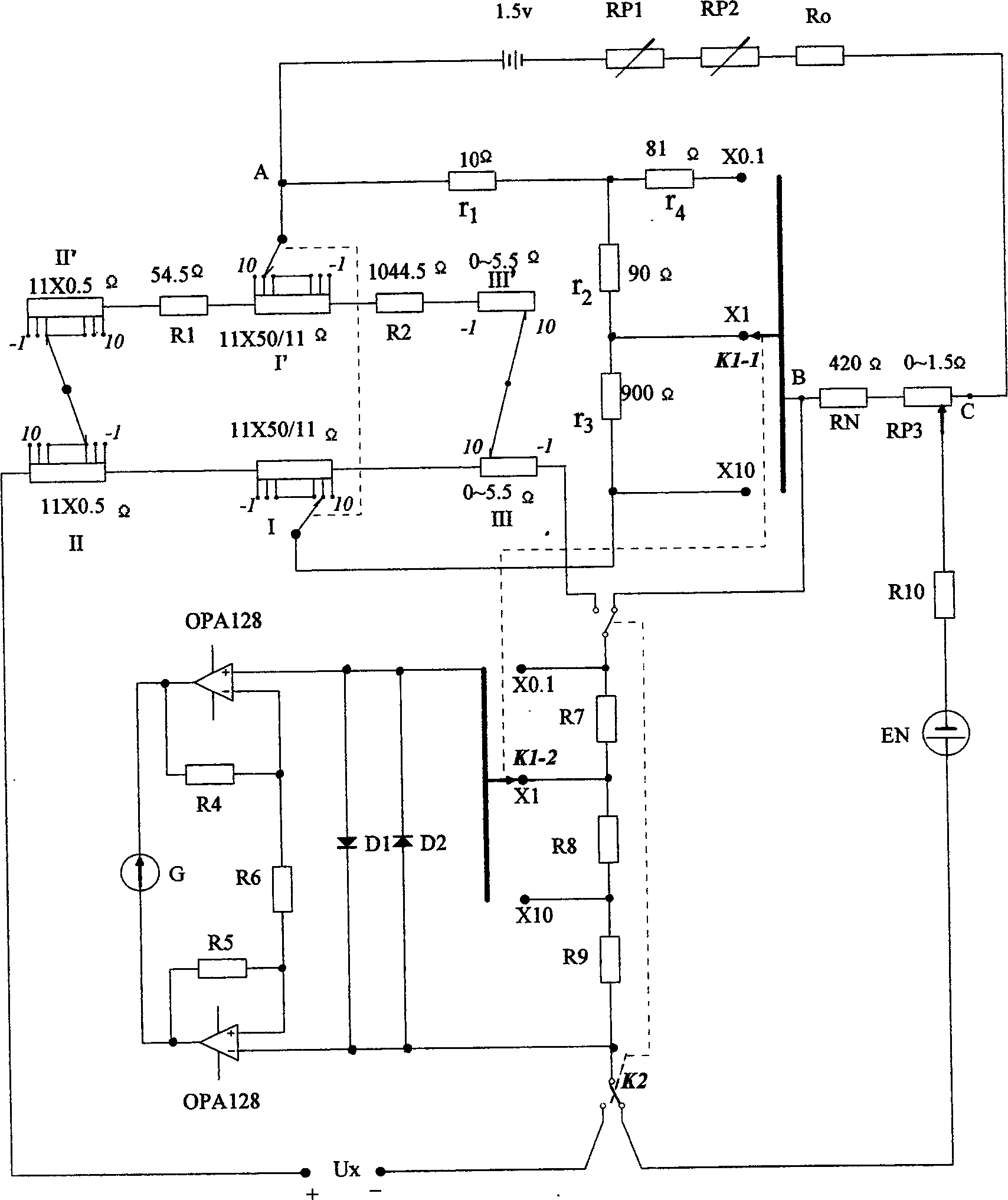
[0010] In the figure, when the three measuring discs throw "-1", the resistance value of the left part between the I' replacement disc brush and the I measuring disc brush is 11×50 / 11Ω+54.5Ω+5.5Ω= 110Ω, the resistance value of the right part is 11×50 / 11Ω+5.5Ω+1044.5Ω=1100Ω, so the total resistance between the two brushes of the first plate is 100Ω, because the measurement plate increases a resistance value, and the change of the plate reduces the same resistance Value, so the resistance value does not change when the measuring disc throws other values. In the ×10 range, the resistance in parallel with the measuring disc is 1000Ω. At this time, the total current flowing through the measuring disc is 2.2mA, and the current on the parallel 1000Ω resistor is 0.22mA. In the ×1 range, the parallel resistance with the measuring disc is 100Ω. The resistance connected in series with the measuring disk is 1000Ω, so the total current flowing through the measuring disk is 0.22mA. Similarl...


PUM


Abstract

The invention provides a portable potentiometer with three-range switching for DC voltage measurement, which includes three ranges of X10, X1 and X0.1, wherein 11X50 / 11 Omega is used as a No:1 measuring disc, 11X0.5 Omega is used as a No:2 measuring disc, 0-5.5 Omega is used as a No:3 measuring disc, the three measuring discs are connected with wires, thus no contact resistance and variation exist, the zero potential produced by the lead wire resistance is compensated through the negative potential, in the X10 range, its high measuring limit is 111mv, in the X0.1 range, its minimum resolution is 0.1uV, and good measurement reproducibility can be achieved.

Description

technical field [0001] The invention relates to an instrument for measuring DC voltage. Background technique [0002] In the current portable potentiometer, due to the switch contact resistance and variation inside the potentiometer used to measure the two terminals, as well as the influence of thermal potential, the resolution of the product cannot be 0.1μV. Contents of the invention [0003] The purpose of the present invention is to design a portable potentiometer, which has three ranges and has a resolution of 0.1 μV when the limit is the smallest. It can eliminate the contact resistance and variation effects between switches, and also excludes the influence of thermoelectric potential; In order to facilitate "self-test", the three measuring discs are all set with "-1" indication value. [0004] The technical scheme of the present invention is as follows: the working current adjustment resistor RP 1 and RP 2 , a fixed resistor R for a fixed supply voltage drop 0 , ...

Claims


Application Information

Patent Timeline
IPC IPC(8): G01R17/20
Inventor 骆乃光
Owner 骆乃光
Learn More