Method for producing injection-molded and in-mold decorated article and mold for injection molding with in-mold decoration

A technology of injection molding and manufacturing method, which is applied in the direction of coating, etc., and can solve the problems of resin burn, shape and layout restrictions of molding space part 503 and auxiliary space part 504, and easy occurrence of fusion lines, etc.

Inactive Publication Date: 2006-04-26
NISSHA PRINTING COMPANY
View PDF0 Cites 6 Cited by
  • Summary
  • Abstract
  • Description
  • Claims
  • Application Information

AI Technical Summary

Problems solved by technology

Moreover, in such a state where gas is likely to remain, the molten molding resins collide with each other near the center of the molding space portion 503, so there is a possibility that Figure 52 As shown in the schematic diagram of the resin molded product 505 in , the resin caused by gas occurs near the center of the resin molded product 505a formed by the molding space 503 (505b in the figure is the resin molded part formed by the auxiliary space 504). burn 552
In addition, if Figure 51 As shown, since the molten molding resins collide with each other near the center of the molding space 503 , weld lines 551 are likely to occur near the center of the resin molded product 505 a formed by the molding space 503 .
[0011] In addition, since the molten molding resin is injected into the molding space 503 through the auxiliary space 504 surrounding the entire circumference of the molding space 503, the injection of the molding resin is substantially uniform in all directions directed to the molding space 503, Therefore, there is a restriction that before filling the molding space 503 with the molding resin, it is necessary to perform molding in the auxiliary space 504 located on the opposite side of the gate 514 across the molding space 503 . resin filling
The existence of such restrictions makes the shape and layout of the molding space 503 and the auxiliary space 504 substantially restricted.

Method used


Image

  • Method for producing injection-molded and in-mold decorated article and mold for injection molding with in-mold decoration
  • Method for producing injection-molded and in-mold decorated article and mold for injection molding with in-mold decoration
  • Method for producing injection-molded and in-mold decorated article and mold for injection molding with in-mold decoration

Examples


no. 1 Embodiment approach

[0163] Next, a first embodiment of the present invention will be described in detail with reference to the drawings. In the drawings used in the description of the respective embodiments of the present invention, the same components are denoted by the same reference numerals.

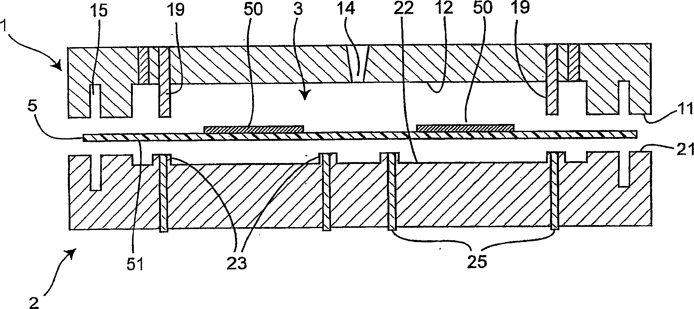
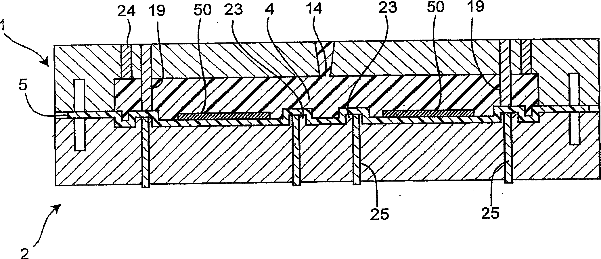
[0164] First, as a schematic explanatory diagram showing a method of manufacturing an injection-molded simultaneous decorative article according to the first embodiment, figure 1 , figure 2 , image 3 and Figure 4 A schematic sectional view of the first mold and the second mold is shown. In addition, the plan view of this 1st mold is as follows Figure 5 as shown, Figure 6A , Figure 6B , Figure 6C and Figure 6D respectively Figure 5 B-B sectional view, C-C sectional view, D-D sectional view, and E-E sectional view of the first mold. In addition, the top view of the second mold is as follows Figure 7 as shown, Figure 8A and Figure 8B show Figure 7 F-F sectional view and G-G sect...

no. 2 Embodiment approach

[0221] The present invention is not limited to the above-mentioned embodiments, but may also be implemented in other schemes. For example, the injection-molded simultaneous decorative article manufacturing method according to the second embodiment of the present invention can be said to be the same method in terms of using the first mold, the second mold, and the decorative film having substantially the same structure as those in the first embodiment. , but in the point that the first mold and the second mold are placed facing each other with the decorative film set in the middle, and the injection of the molding resin is performed in the state where each mold is opened without clamping the molds, it is different from the above-mentioned first mold. The method of implementation is different. That is, in the second embodiment, the injection of the molding resin is performed in a state where the molding space formed between the first mold and the decorative film is open (that is...

Embodiment 1

[0238] In each of the above-mentioned embodiments, a description has been given in which the molding space 3 is formed by four product molding spaces 31, the molding space 32 for resin injection, and the molding space 33 for resin discharge, but it is not limited thereto. Although there are not only a plurality of product molding spaces but also resin injection molding spaces, various options are conceivable.

[0239] Here, a spatial layout diagram (schematic plan view) of the molding space portion 110 according to the first embodiment is shown in Figure 23 . Such as Figure 23 As shown, the molding space portion 110 is formed by a product molding space portion 111 and a molding space portion 113 for resin discharge. Specifically, the product molding space 111 is a substantially square-shaped space in plan view, and the resin discharge molding space 113 is provided so as to surround the entire outer periphery of the product molding space 111 . In addition, a gate portion 1...


PUM


Abstract

In a manufacturing method for injection-molded and in-mold decorated articles including injection of molding resin (4) into a molding space (3) defined by a decorating film (5) and a mold (1), the molding space has a product molding space (31) and a resin-discharging-use molding space (33) which is formed around the product molding space and into which the molding resin is let to flow for discharge of the molding resin from the product molding space. The molding resin is injected into the product molding space, and while part of the injected molding resin is discharged from the product molding space into the resin-discharging-use molding space, the molding resin is filled into the product molding space.

Description

technical field [0001] The present invention relates to a method of manufacturing an injection-molded simultaneous decoration and a mold for injection-molded simultaneous decoration used in the production. The method comprises arranging a decorative film between a first mold and a second mold that are arranged to face each other, Molten molding resin is injected into the molding space formed by the above-mentioned decorative film and the above-mentioned first mold, the above-mentioned molding resin filled in the above-mentioned molding space by the injection is solidified, and the surface of the molding resin is treated with the above-mentioned decorative film. decorate. Background technique [0002] In recent years, there has been an increasing demand for thinner and thinner molded products and various parts of electronic equipment. As a method of manufacturing resin molded products using an injection molding mold composed of a molding space corresponding to the shape of e...

Claims


Application Information

Patent Timeline
Patent Type & Authority Applications(China)
IPC IPC(8): B29C45/14B29C45/26
Inventor 古川英次丰冈尚登
Owner NISSHA PRINTING COMPANY
Why Eureka
Try Eureka