
Compressor base angle

A compressor and bottom angle technology, which is applied in the direction of mechanical equipment, machines/engines, liquid variable capacity machines, etc., can solve problems such as uneven gaps and increased compressor noise, and achieve the goals of saving materials, avoiding resonance, and reducing costs Effect

Inactive Publication Date: 2006-04-26
LG ELECTRONICS (TIANJIN) APPLIANCES CO LTD
View PDF0 Cites 3 Cited by
  • Summary
  • Abstract
  • Description
  • Claims
  • Application Information

AI Technical Summary

Problems solved by technology

Moreover, the contact gap between the bottom cover of the compressor casing and other parts of the bottom angle 8 is also very small, and the gap is not uniform.
As a result, resonance is generated when the compressor is working, which increases the noise of the compressor

Method used


Image

  • Compressor base angle
  • Compressor base angle

Examples


Embodiment Construction

[0017] The bottom angle of the compressor of the present invention will be described below in conjunction with the accompanying drawings and embodiments.

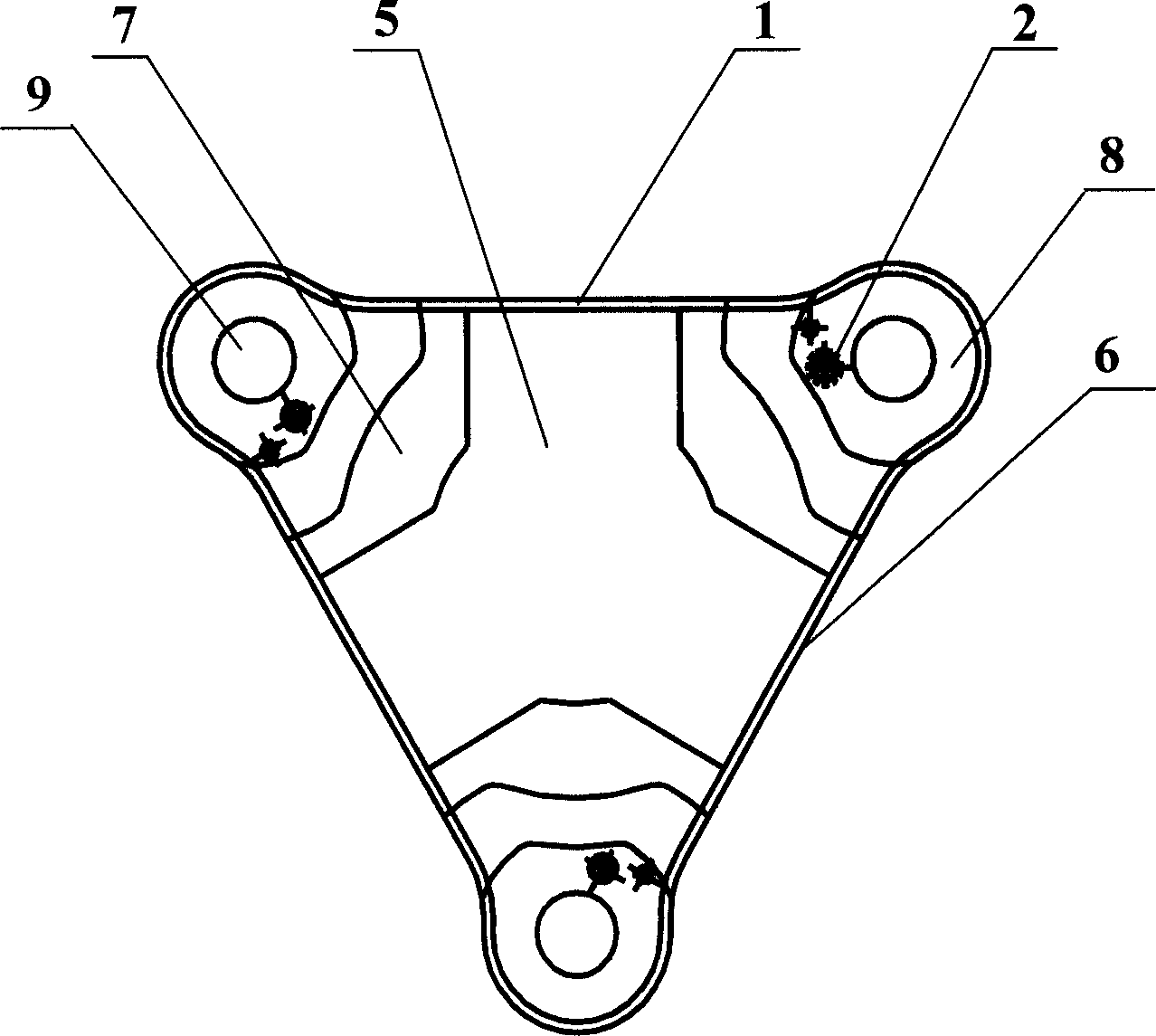
[0018] Such as figure 2 As shown, the bottom corner of the compressor includes an edge 6 constituting its edge and a support angle 8 for support at each corner of the bottom corner 1 of the triangle, which is formed in the middle of the bottom corner 1 and around the inner side of the edge 6 There is a hollow portion 5 , and a bottom surface 7 is formed between the hollow portion 5 and each support angle 8 . The three support angles 8 are formed by inclining from the bottom surface 7 for a section and then extending horizontally outward. A round hole 9 is formed in the center of each top angle 8, and the round hole 9 is used for installing a shock absorber supporting the compressor.

[0019] The edge 6 on the corner 1 forms the three sides of the corner 1 .

[0020] When assembling the compressor, place the bottom cover ...


PUM


Abstract

The invention discloses a compressor base-angle, which comprises the following parts: edge on triangle base angle, support angle, hollow part in the middle of base angle and around inter edge, base face between hollow part and each support angle. The invention increases the gap between base angle and compressor after welding the compressor base cover and base angle, which reduces the structure noise and affirms the centring due to removing part of base face in the base angle.

Description

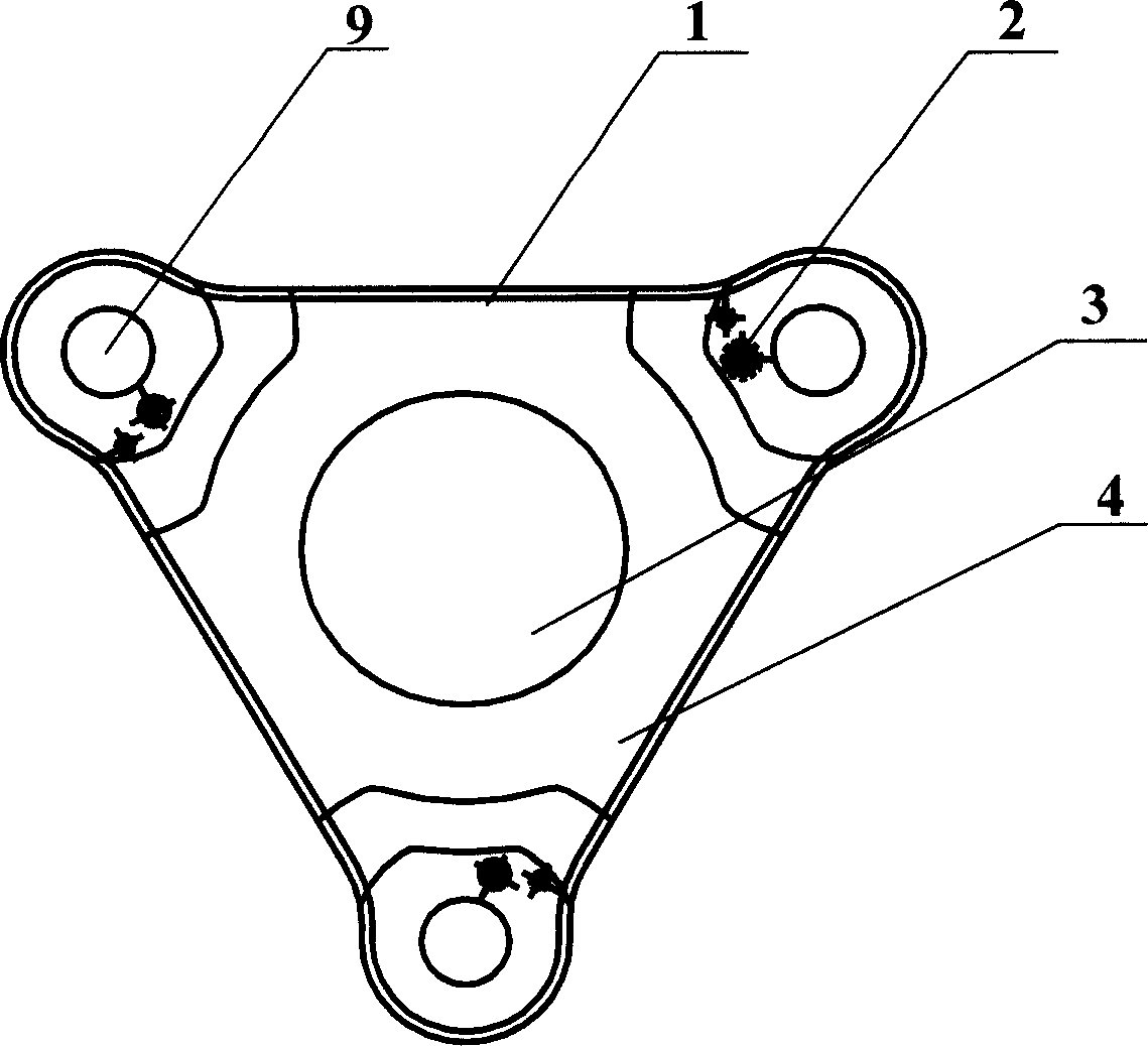
technical field [0001] The invention relates to a bottom angle of a compressor. In particular, it relates to a bottom angle of a compressor that can reduce resonance and reduce structural noise of the compressor. Background technique [0002] A compressor is a device that compresses a fluid. It usually consists of a sealed housing with an internal space, an electromechanical part installed in the sealed housing and providing driving force, and a compression mechanical part driven by the electromechanical part to compress the refrigerant. The compressor includes a cylindrical housing having a compression mechanical part and a bottom corner provided on a lower side of the housing 1 and having a triangular structure. [0003] Such as figure 1 As shown, a bottom surface 4 is formed on the bottom corner 1, and a circular hollow portion 3 is formed at the center of the bottom surface 4, while the three supporting corners 8 at the top of the bottom corner 1 are inclined from the...

Claims


Application Information

Patent Timeline
Patent Type & Authority Applications(China)
IPC IPC(8): F04B39/00F04C29/06
Inventor 刘永利
Owner LG ELECTRONICS (TIANJIN) APPLIANCES CO LTD
Learn More