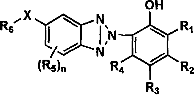
Method for manufacturing optical film and optical film, polarizing plate and display
A technology for an optical film and a manufacturing method, which is applied in the fields of optical films, polarizers and display devices, can solve the problems of rib-like failure of the anti-reflection layer of the active ray-cured resin layer, and white turbidity of the film, and achieves less whitening spots and less color spots. Effect
- Summary
- Abstract
- Description
- Claims
- Application Information
AI Technical Summary
Problems solved by technology
Method used
Image
Examples
Embodiment 1
[1408] (Production of Optical Films 1-29)
[1409] The above-mentioned cellulose resin was heat-treated at 120° C. in dry air for 1 hour, and left to cool to room temperature in dry air. With respect to 90 parts by mass of dry cellulose resin, plasticizers and additives other than the above-mentioned cellulose resin were added in the composition of Table 1, mixed with a Henschel mixer, and then heated using an extruder to make pellets. Let it cool.
[1410] After the pellets were dried at 120°C, they were heated and melted at the melting temperature shown in Table 1 using an extruder, and immediately extruded from a T-shaped die, passed through a stretching roll at 158°C to obtain a film at a roll temperature Stretch 1.05 times in the longitudinal direction, then use a tenter to stretch 1.2 times in the width direction and then relax. While cooling, remove the ears at both ends of the width direction by cutting, and then cool to room temperature (20°C). Embosses with a heigh...
Embodiment 2
[1430] "Making of Polarizers"
[1431] Using the optical films 1 to 17 and 19 to 29 produced in Example 1, a hard coat layer and an antireflection layer were formed on one surface thereof to produce antireflection films 1 to 17 and 19 to 29 with a hard coat layer. Polarizing plates 1 to 17 and 19 to 29 were fabricated using this.
[1432]
[1433] The following hard coat composition was applied so as to have a dry film thickness of 3.5 μm, and dried at 80° C. for 1 minute. Then use a high-pressure mercury lamp (80W) at 150mJ / cm 2 It is cured under certain conditions to produce a hard coat film with a hard coat layer. The hard coat layer had a refractive index of 1.50.
[1434]
[1435] 108 parts by mass of dipentaerythritol hexaacrylate (contains about 20% or more components of dimers)
[1436] イルガクユア184 (manufactured by Chiba Specialty Chemicals Co., Ltd.) 2 parts by mass
[1437] 180 parts by mass of propylene glycol monomethyl ether
[1438] 120 parts by mass of e...
Embodiment 3
[1517] Except that the optical film 18 produced in Example 1 was used as the polarizer protection film on the back side instead of the Konika Minolta Tac KC8UCR-4 (manufactured by Konika Minolta Opto Co., Ltd.) used in Example 2 as the polarizer protective film on the back side. Outside the film, a polarizing plate and a liquid crystal display device were produced in the same manner. As a result, it was confirmed that Example 2 was reproduced. The polarizing plate and the liquid crystal display device using the optical film and the antireflection film of the present invention also had no problem of reflection color spots, and had excellent visibility.
PUM
| Property | Measurement | Unit |
|---|---|---|
| acid value | aaaaa | aaaaa |
| hydroxyl value | aaaaa | aaaaa |
| acid value | aaaaa | aaaaa |
Abstract
Description
Claims
Application Information
 - R&D
- Intellectual Property
- Life Sciences
- Materials
- Tech Scout
- Unparalleled Data Quality
- Higher Quality Content
- 60% Fewer Hallucinations
Browse by: Latest US Patents, China's latest patents, Technical Efficacy Thesaurus, Application Domain, Technology Topic, Popular Technical Reports.
© 2025 PatSnap. All rights reserved.Legal|Privacy policy|Modern Slavery Act Transparency Statement|Sitemap|About US| Contact US: help@patsnap.com


