Clock, signal multiplex method and system
A clock and signaling technology, applied in the field of signaling multiplexing method and system, and clock, can solve problems such as high cost and complex system design, achieve the effect of reducing implementation cost, reducing interface resources, and improving scalability
- Summary
- Abstract
- Description
- Claims
- Application Information
AI Technical Summary
Problems solved by technology
Method used
Image
Examples
no. 1 example
[0087] In this example,
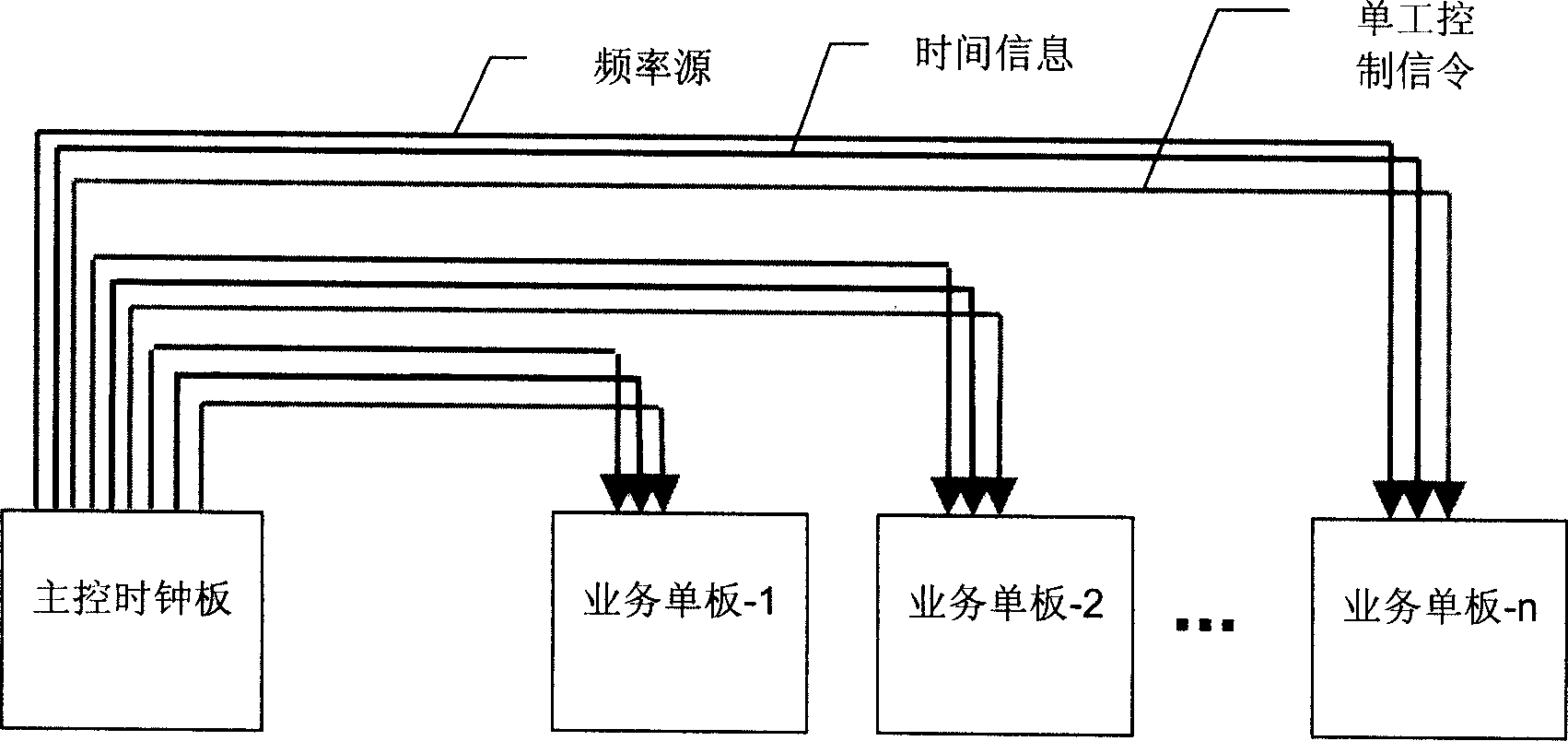
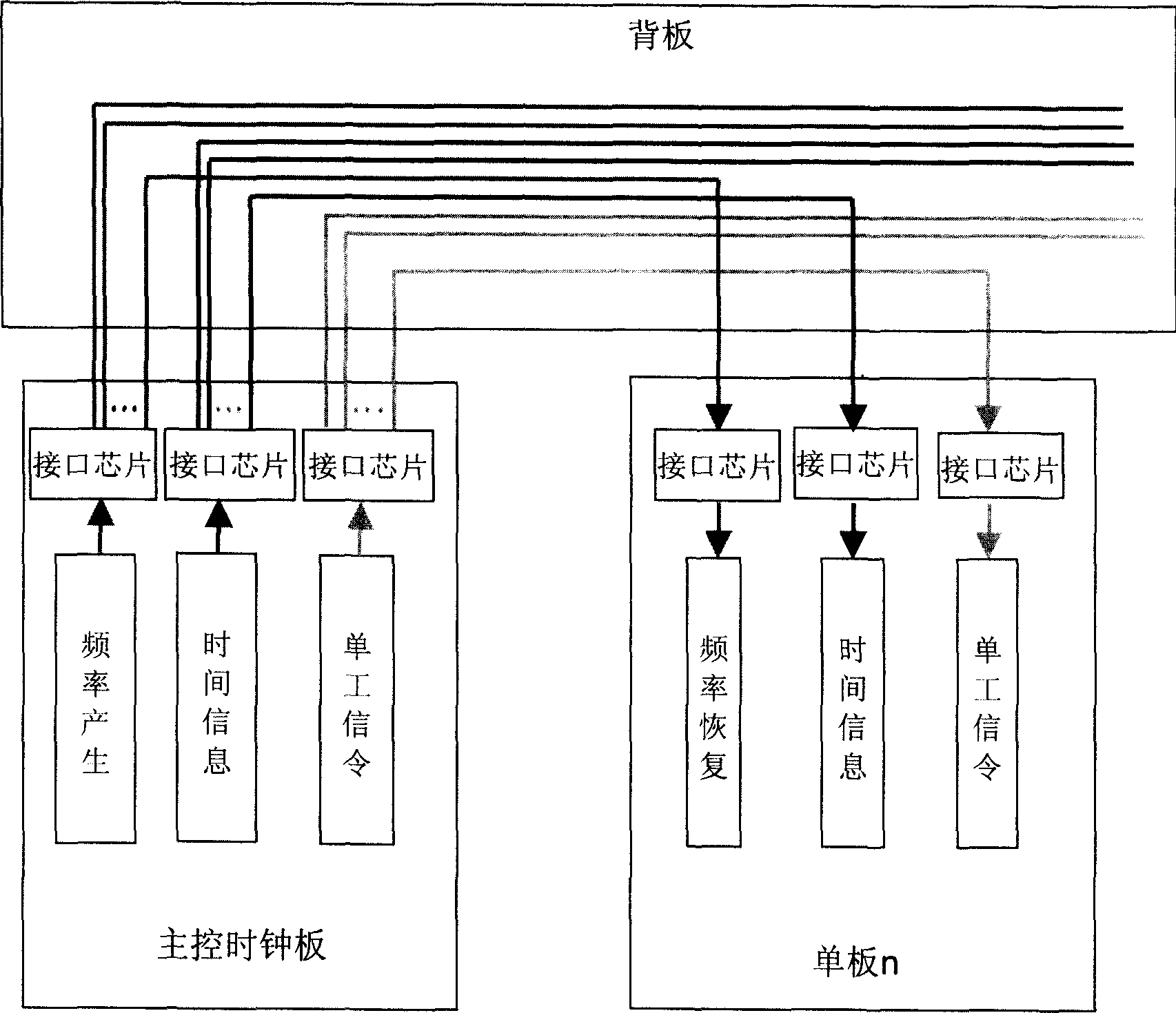
[0088] The master clock board 60 includes: a clock source module 601 for generating a reference frequency source; a timing information generation module 602 for generating system timing information; a simplex signaling generation module 603 for generating system simplex signaling.
[0089] In addition, the main control clock board 60 also includes:
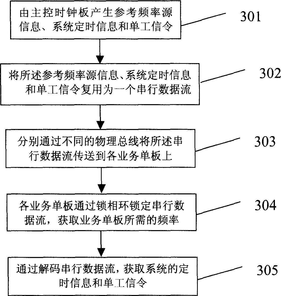
[0090] The encoding module 604 is respectively coupled to the clock source module, the timing information generation module and the simplex signaling generation module, and is used to multiplex the reference frequency source, system timing information and simplex signaling into a serial data stream output;
[0091] The output interface module 605 is coupled to the encoding module 604, and is used to output the serial data stream to the service board through the physical bus L1.
[0092] Service single board 61 includes:
[0093] An input interface module 615 for receiving the serial data stream input by...
no. 2 example
[0097] In order to make the encoding strictly synchronized with the system clock when the system timing information and simplex signaling are encoded, in this embodiment, an encoding phase-locked loop module 606 is connected between the clock source module 601 and the encoding module 604, through This module ensures that the frequency of the serial data stream output by the encoding module is consistent with the frequency of the reference frequency source generated by the clock source module.
[0098] Similarly, on the service board, in order to obtain the frequency required by the service board strictly synchronized with the system from the input serial data stream, so as to ensure that each service board works synchronously with the system. A frequency recovery module 616 is connected between the input interface module 615 and the decoding PLL module 611 . Since the serial data stream output by the input interface module contains system timing and signaling information, the ...
PUM
 Abstract
Description
Claims
Application Information
 - R&D
- Intellectual Property
- Life Sciences
- Materials
- Tech Scout
- Unparalleled Data Quality
- Higher Quality Content
- 60% Fewer Hallucinations
Browse by: Latest US Patents, China's latest patents, Technical Efficacy Thesaurus, Application Domain, Technology Topic, Popular Technical Reports.
© 2025 PatSnap. All rights reserved.Legal|Privacy policy|Modern Slavery Act Transparency Statement|Sitemap|About US| Contact US: help@patsnap.com


