
Patsnap Eureka
For R&D, Patsnap Eureka makes reading and utilizing patents & technical documents easy.
Patsnap Eureka AIR
Designed for self-driven R&D workflows. Generate viable solutions, solve complex R&D challenges, empower your innovation with AI.

Patsnap Eureka Materials
Designed for material experts only. Revolutionize your material R&D, from search, analyze, to developing new materials.

TechResearch
Generate reliable direction feasibility study reports for your R&D in just a few steps.

TechSeek
Discover and master advanced knowledge NOW. Basics, ideas, possibilities, all at once.

TechMind
As an expert in R&D Theories, TechMind can generates customized viable solutions instantly.

TechRisk
Analyze your overall solution with one click, know your potential R&D risks in advance.

TechMonitor
Get weekly tech updates, stay abreast of the latest tech innovations and key insights.
Device of representing a video image based on video frequency signal
A video signal and video image technology, applied in the field of devices representing video images based on video signals, can solve problems such as short life expectancy
- Summary
- Abstract
- Description
- Claims
- Application Information
AI Technical Summary
Problems solved by technology
Method used
Image

Examples
Embodiment Construction
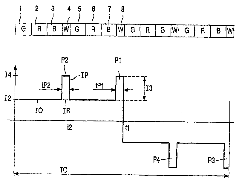
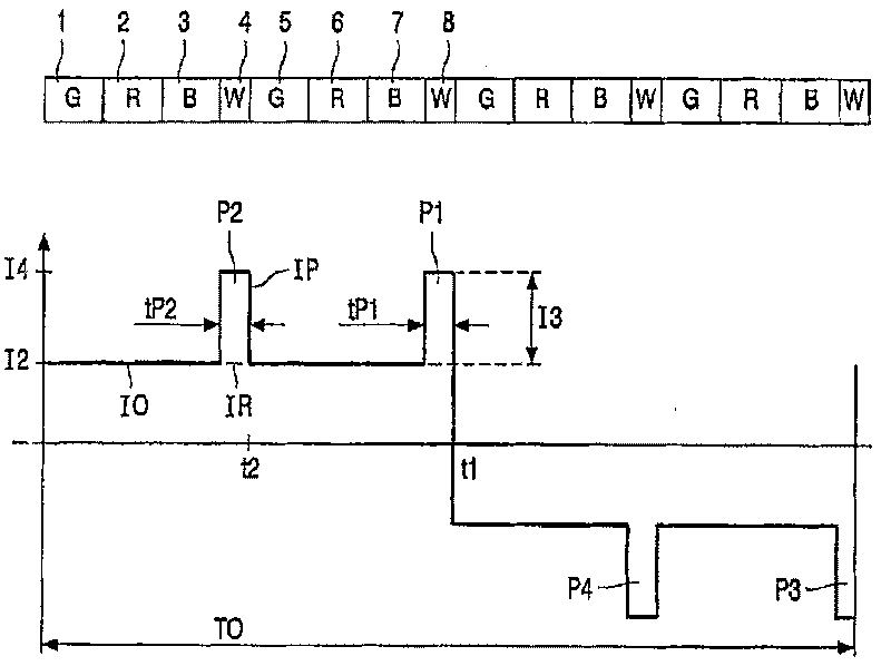
[0023] figure 1 is a time diagram with a square-wave pulsating alternating current 10, the period of which has a duration of TO. The square-wave pulsating alternating current 10 is composed of a square-wave alternating current IR and a pulsating current IP. TO equals 16 ms, or a video frequency of 60 Hz as used in NTSC video systems. The first pulse P1 ends at instant t1, ie after half a period before inversion. This square-wave pulsating alternating current 10 comprises a second pulse P2 which ends at time t2, ie after a quarter of a period. The magnitude of this square-wave alternating current IR is denoted I2. The pulses P1 and P2 are components of the pulsating current IP with pulse durations tP1 and tP2, amplitude I3 and the same profile. When an alternating current IR and a pulsating current IP having the same polarity are superimposed, the result is a pulsating square-wave alternating current I0 whose highest amplitude is I4. A total of four pulses P1, P2, P3 and P...
PUM
 Abstract
Description
Claims
Application Information
 - R&D Engineer
- R&D Manager
- IP Professional
- Industry Leading Data Capabilities
- Powerful AI technology
- Patent DNA Extraction
Browse by: Latest US Patents, China's latest patents, Technical Efficacy Thesaurus, Application Domain, Technology Topic, Popular Technical Reports.
© 2024 PatSnap. All rights reserved.Legal|Privacy policy|Modern Slavery Act Transparency Statement|Sitemap|About US| Contact US: help@patsnap.com