Motor vibration exciter

A vibration exciter and motor technology, applied in the direction of using vibration fluid, etc., can solve the problems of easy breakage of anchor bolts, large manufacturing workload, cumbersome assembly and maintenance, etc. The effect of the force condition

Inactive Publication Date: 2006-02-22
樊振江
View PDF1 Cites 1 Cited by
  • Summary
  • Abstract
  • Description
  • Claims
  • Application Information

AI Technical Summary

Problems solved by technology

Since the rotor shaft of the vibrating motor rotates, the centrifugal inertial force is large and acts on the cantilever end of the rotor shaft outside the bearing. The bearings of the vibrating motor and the anchor bolts are subjected to alternating forces and moments, so the bearings wear quickly and the temperature rises. Bolts are also prone to breakage
Although the invention patent (Patent No. ZL01251697.X) owned by me completely solves the two problems of short life of vibration motor bearings and easy breakage of anchor bolts by adopting a mechanically superstatic structure, its structure is relatively more complex than that of known vibration motors. Complicated, which makes the manufacturing workload larger and the assembly and maintenance more cumbersome

Method used


Image

  • Motor vibration exciter

Examples


Embodiment Construction

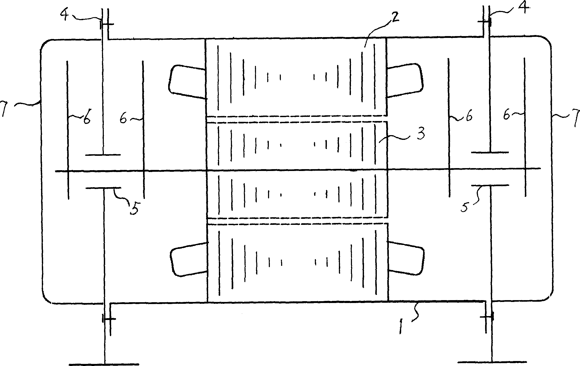
[0009] As shown in the figure, the motor exciter of the present invention includes a casing 1, a stator and a rotor 2, 3 arranged in the casing 1, and two ports of the casing 1 are connected to the bearing housing 4 respectively. fixed connection; both ends of the rotor shaft respectively pass through the bearing holes on the bearing seat 4; eccentric mass blocks 6 are symmetrically fixed on the rotor shafts located on both sides of the bearing 5; The two ports of the two ports are respectively provided with shields 7 which are fixedly connected with the bearing housing 4 .


PUM


Abstract

The invention discloses a motor exciting device, which comprises a shell, a stator and rotor equipped with said shell; the two ends of said shell being separately equipped with bearing block; the two ends of said rotor shaft passing separately across the bearing hole of said bearing block; the rotor shafts locating on the two sides of said bearing being separately equipped with eccentric mass block; the two ports of said shell being separately equipped with guard which is linked with said bearing block. Compared with the domestic prior vibration electromotor, the invented has a simple structure and a low cost as the same, and it prolongs the life time of the bearing and the foundation bolt with said structure; compared with the foreign inertial vibration source of fluid-pressure driving eccentric block, the invented has a much simpler structure.

Description

technical field [0001] The invention relates to an inertial vibrator, in particular to a motor vibrator which generates an inertial force vibration source. Background technique [0002] At present, most of the known inertial exciters are vibrating motors. The structure of the vibrating motor is: the two ends of the rotor shaft of the common motor are extended, and two groups of eccentric masses are symmetrically fitted on the two extended ends. When the rotor shaft rotates, the eccentric mass rotates with it to generate alternating centrifugal inertial force to form a vibration source. Since the rotor shaft of the vibrating motor rotates, the centrifugal inertial force is large and acts on the cantilever end of the rotor shaft outside the bearing. The bearings of the vibrating motor and the anchor bolts are subjected to alternating forces and moments, so the bearings wear quickly and the temperature rises. Bolts are also prone to breakage. Although the invention patent (Pa...

Claims


Application Information

Patent Timeline
Patent Type & Authority Applications(China)
IPC IPC(8): B06B1/16
Inventor 樊振江樊晓冰樊梦樊暮雪
Owner 樊振江
Why Eureka
Try Eureka