Jet tray with large liquid holdup
A liquid holdup and tray technology, applied in the field of large liquid holdup injection trays, can solve the problems of small operating flexibility, difficult control, and low tray efficiency
Inactive Publication Date: 2006-02-22
HEBEI UNIV OF TECH
View PDF0 Cites 11 Cited by
- Summary
- Abstract
- Description
- Claims
- Application Information
AI Technical Summary
Benefits of technology
This technology allows for precise control over how much material will form during chemical reaction processes by controlling the depth at which certain materials come into contact with each other or react together (the size) inside one tank called an “reaction vessel". By doing that, it becomes possible to create high purity products without contamination from unwanted substances produced along sidewalls of these vessels.
Problems solved by technology
This patented technology describes an improvement over existing methods for separating liquids from gases by reacting them together under specific conditions such as temperature and pressure. However, there still needs improvements due to limitations like high pressures during operation caused by excessive gas accumulation inside certain parts of the system's equipment.
Method used
View moreImage
Smart ImageViewing Examples

Examples
 PUM
| Property | Measurement | Unit |
|---|---|---|
| Height | aaaaa | aaaaa |
| Height | aaaaa | aaaaa |
Abstract
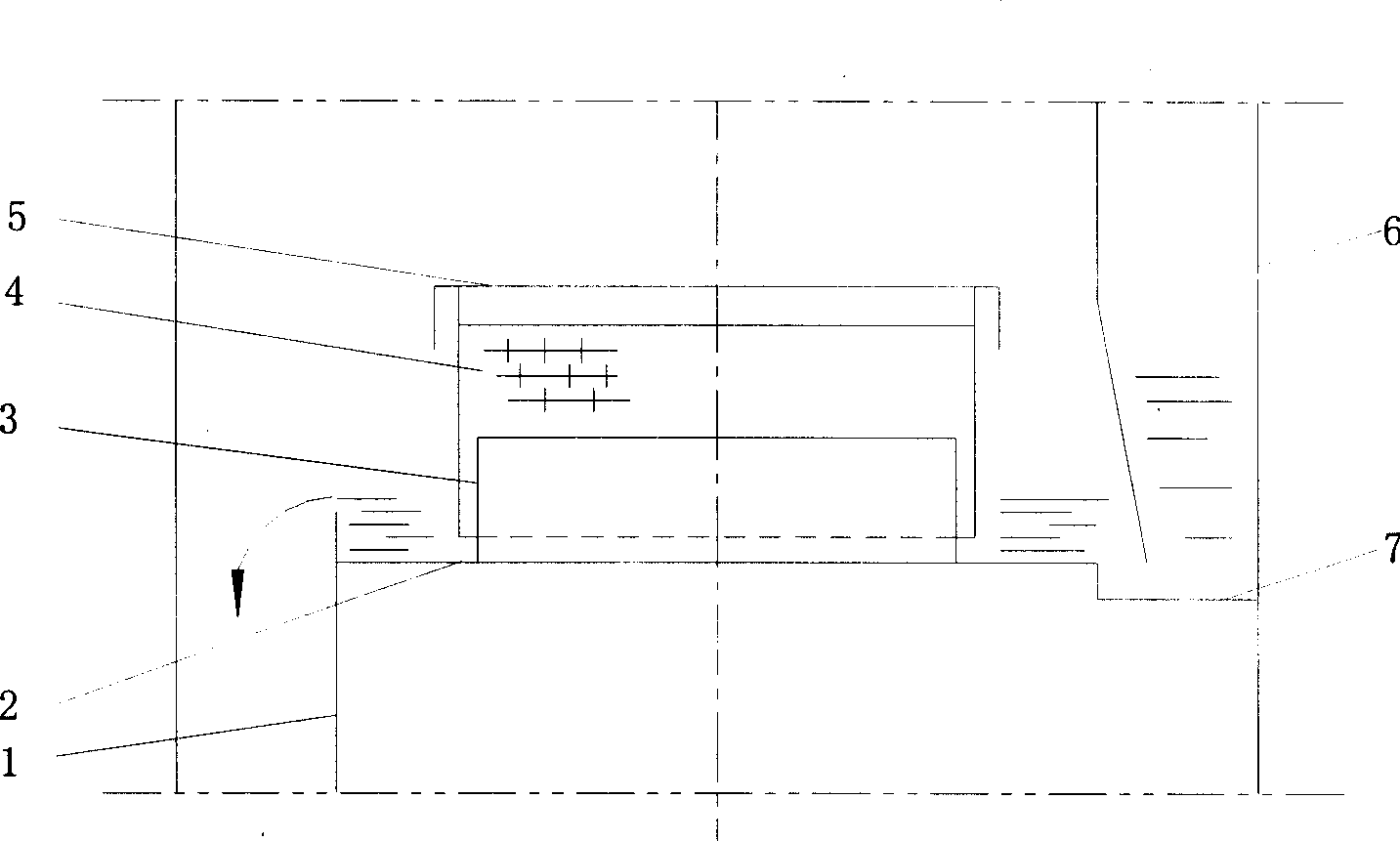
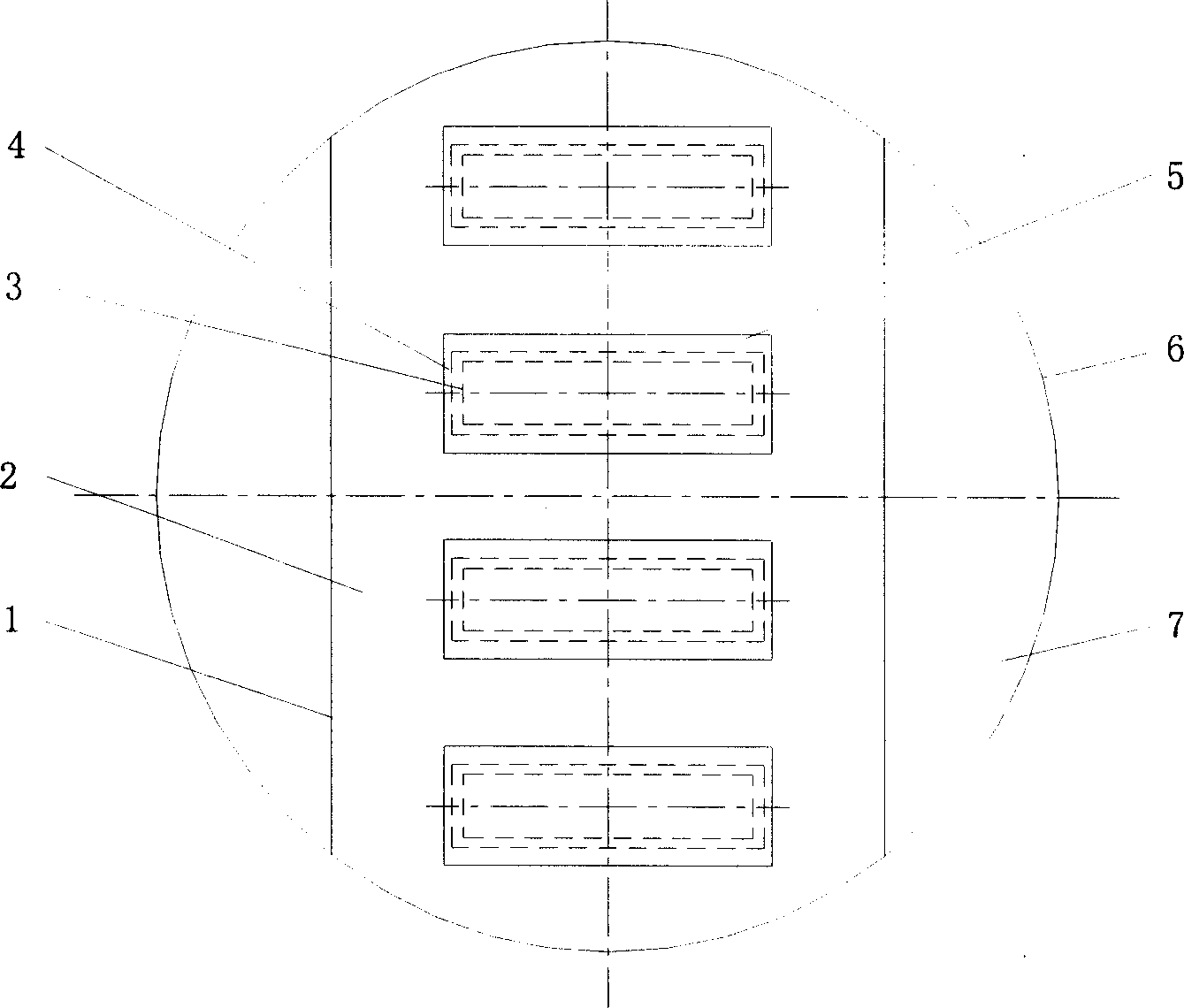
The invention relates to an injection column plate of a large liquid capacity. Injection unit structure of the column plate is described as the following: the column plate being equipped with regularly arranged ascending-pipe, which is equipped with injection cover, and a slot between the ascending-pipe and the injection cover, the injection cover which has an injecting hole in it, being equipped with a gas-liquid separation plate on the top. Compared with the common float valve plate and sieve-plate column, the injection column plate is easy to adjustment and control, and it can perfectly satisfy the technical requirement of distillation. And by adjusting the liquid capacity of the column plate, the reaction time can be controlled. When the column space is the custom 600mm, the height of supernatant layer on the column plate can be adjusted randomly at a range of 20- 400mm to satisfy the requirement of liquid capacity.
Description
Login to View More Claims
Login to View More Application Information
Patent Timeline
 Owner HEBEI UNIV OF TECH
Features
- Generate Ideas
- Intellectual Property
- Life Sciences
- Materials
- Tech Scout
- Unparalleled Data Quality
- Higher Quality Content
- 60% Fewer Hallucinations
Learn More Browse by: Latest US Patents, China's latest patents, Technical Efficacy Thesaurus, Application Domain, Technology Topic, Popular Technical Reports.
© 2025 PatSnap. All rights reserved.Legal|Privacy policy|Modern Slavery Act Transparency Statement|Sitemap|About US| Contact US: help@patsnap.com