Planetary differential screw-type rotational motion/linear motion converter
A differential thread, linear motion technology, applied in the direction of transmission, belt/chain/gear, mechanical equipment, etc., can solve the problems of poor assembly performance, inability to reduce the linear displacement of the threaded shaft of the roller nut, etc. Excellent load performance
- Summary
- Abstract
- Description
- Claims
- Application Information
AI Technical Summary
Problems solved by technology
Method used
Image

Examples
no. 1 example 1
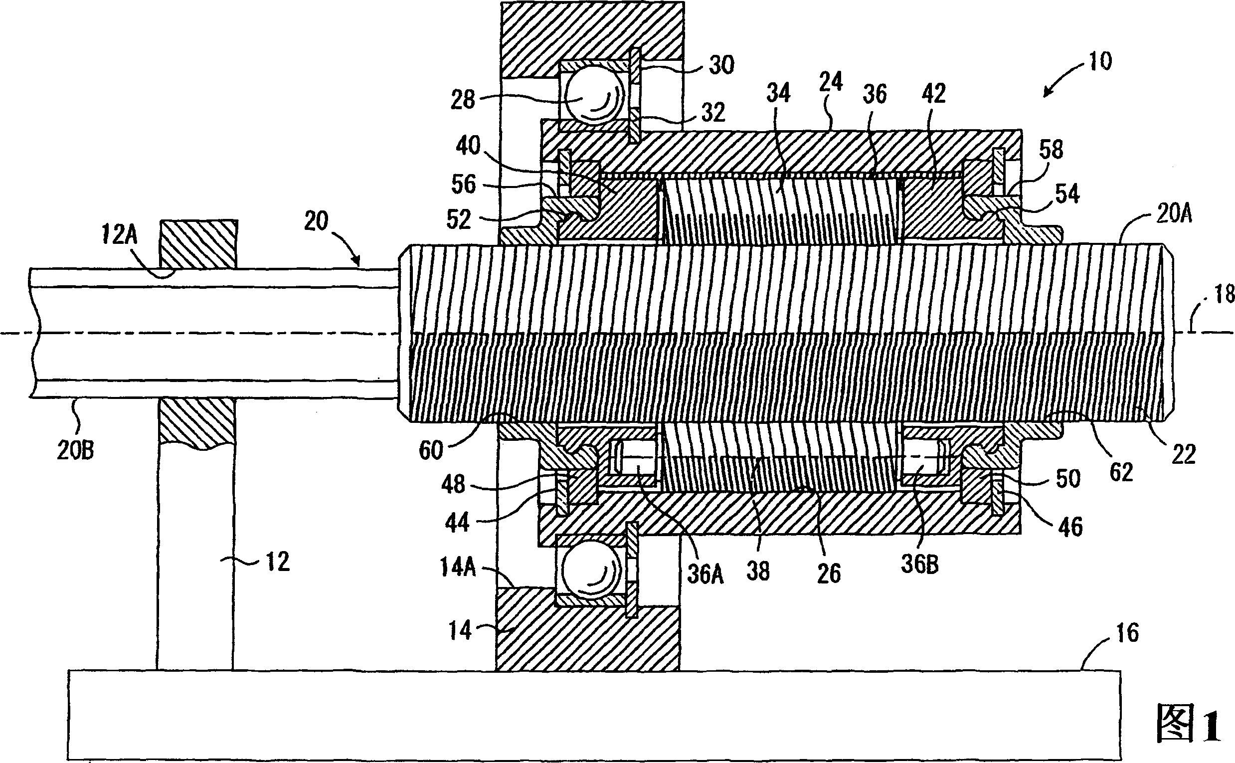
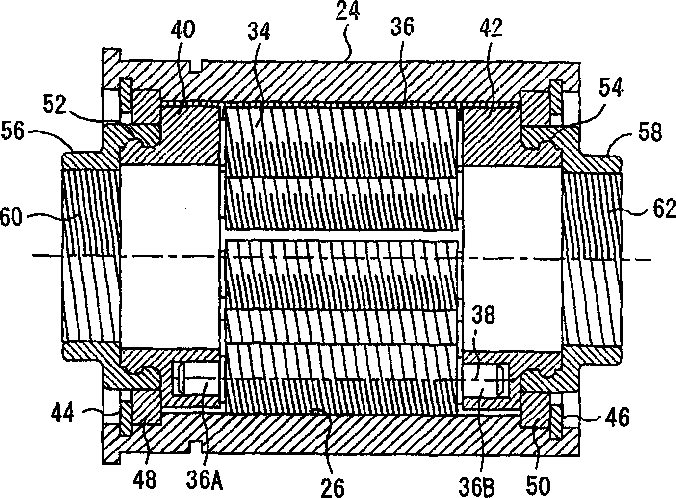
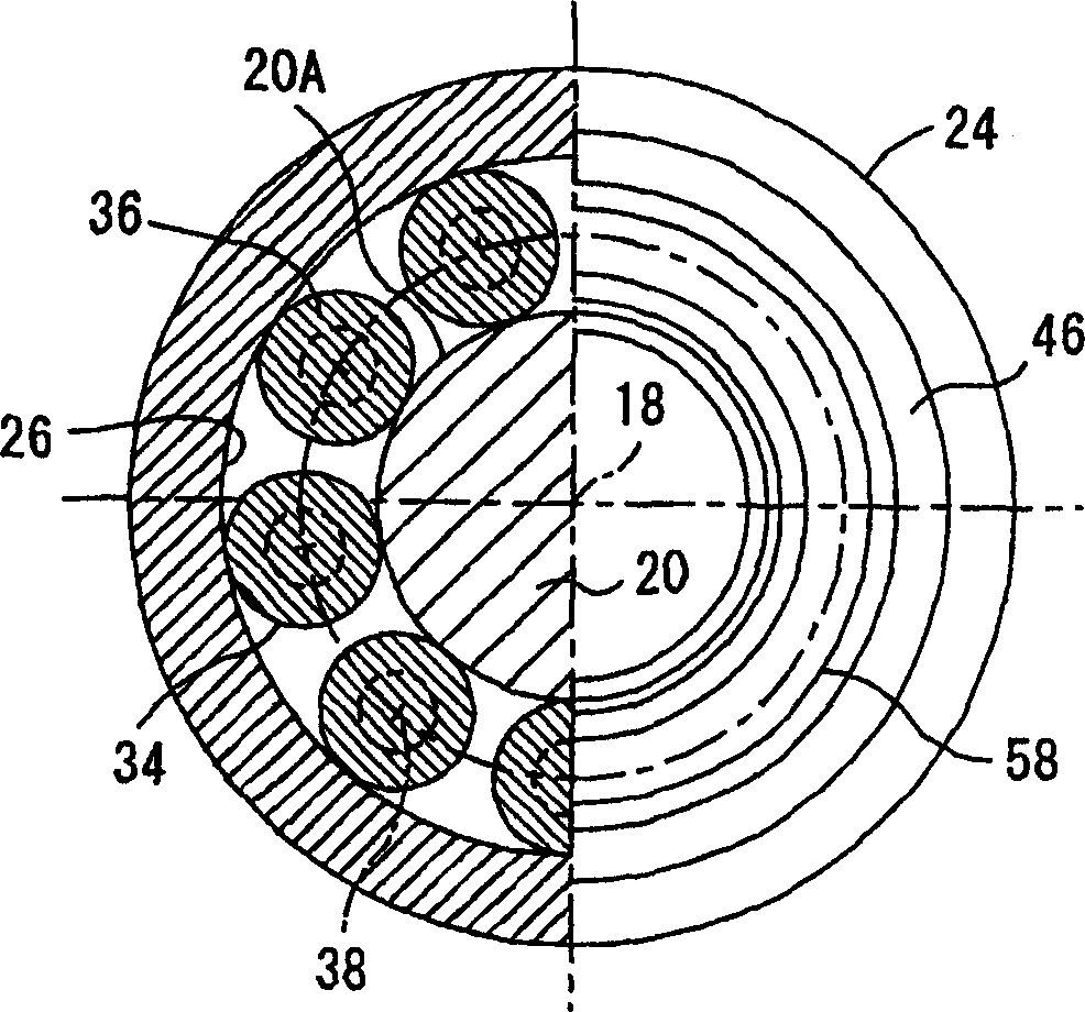
[0108] Fig. 1 is a longitudinal sectional view showing a first embodiment of a planetary differential screw type rotation-linear motion conversion device of the present invention which converts the rotational motion of a roller nut into the linear motion of a threaded shaft, figure 2 It is a front sectional view showing the main part of the first embodiment with the screw shaft removed, image 3 It is a figure showing the right side (right half) and the longitudinal section (left half) perpendicular to the axis of the first embodiment, Figure 4 is the left side view of the first embodiment.
[0109] In these figures, 10 generally denotes a planetary differential screw type rotary-linear motion conversion device, and the rotary-linear motion conversion device 10 is supported by a base 16 via two columns 12 and 14 . The rotation-linear motion conversion device 10 includes a threaded shaft 20 extending along the axis 18. The threaded shaft 20 includes a threaded portion 20A wit...
no. 2 example
[0148] Fig. 7 is a longitudinal sectional view showing a second embodiment of the planetary differential screw type rotary-linear motion conversion device of the present invention which converts the rotational motion of the roller nut into the linear motion of the threaded shaft. In addition, in FIG. 7, the same components as those shown in FIG. 1 are given the same reference numerals as those in FIG.
[0149] In this second embodiment, in the large-diameter portion 20C corresponding to the threaded portion 20A of the first embodiment, the threaded portion 20A is provided only at the central portion opposite to the planetary thread roller 36 , and at both ends of the large-diameter portion 20C The external thread 22 is not provided at the top. In addition, the wheel frames 40 and 42 are the same as the case of the first embodiment, and the relative threaded shaft 20 and the roller nut 24 can rotate relatively, but they are respectively arranged to pass through the C-shaped rin...
no. 3 example
[0157] Fig. 8 is a longitudinal sectional view showing a third embodiment of the planetary differential screw type rotary-linear motion conversion device of the present invention constituted as a modified example of the first embodiment. In addition, in FIG. 7, the same components as those shown in FIG. 1 are marked with the same reference numerals as in FIG. 1, or L or R are added to the reference numerals in FIG.
[0158] The motion transforming device 10 of this third embodiment has a first motion transforming unit 10L and a second motion transforming unit 10R having the same structure as the motion transforming device 10 of the above-mentioned first embodiment, the first motion transforming unit 10L and the second motion transforming unit 10L The motion transformation units 10R are mated to each other along axis 18 while being in mirror image relationship to each other. The male screw 22L of the screw shaft 20L of the first motion conversion unit 10L, the male screw 34L of...
PUM
| Property | Measurement | Unit |
|---|---|---|
| Pressure angle | aaaaa | aaaaa |
Abstract
Description
Claims
Application Information
 - R&D
- Intellectual Property
- Life Sciences
- Materials
- Tech Scout
- Unparalleled Data Quality
- Higher Quality Content
- 60% Fewer Hallucinations
Browse by: Latest US Patents, China's latest patents, Technical Efficacy Thesaurus, Application Domain, Technology Topic, Popular Technical Reports.
© 2025 PatSnap. All rights reserved.Legal|Privacy policy|Modern Slavery Act Transparency Statement|Sitemap|About US| Contact US: help@patsnap.com