
Bipolar zero-gap electrolytic cell

An electrolytic cell, bipolar technology, applied in the direction of electrolysis process, electrolytic components, electrode shape/type, etc., can solve the problems of inability to obtain sufficient wave elimination effect, inability to completely prevent vibration, and inability to prevent unit cell vibration, etc.

Inactive Publication Date: 2006-01-04
ASAHI KASEI KK
View PDF20 Cites 16 Cited by
  • Summary
  • Abstract
  • Description
  • Claims
  • Application Information

AI Technical Summary

Problems solved by technology

[0011] In JP-A No. 61-19789 and JP-A-63-11686, although it is considered that the gas and electrolyte are not pumped to the upper part but are pumped downward, the liquid and gas are still sometimes discharged in mixed phases, which cannot prevent Vibration occurs in the unit electrolyzer
In addition, in order to make the electrolyte concentration inside the tank uniform, a conductive dispersion or a current distribution member that can circulate the electrolyte inside is provided, but the disadvantage is that the structure inside the electrolytic tank becomes complicated.
[0012] In the official publication No. 57-153376, as a countermeasure to prevent vibration in the electrolytic tank, the scheme of the wave-absorbing plate is proposed, but only by this scheme can not obtain sufficient wave-absorbing effect, and cannot completely prevent vibration caused by vibration in the electrolytic tank. Vibration caused by pressure changes
[0013] In JP-A-4-289184 and JP-A-8-100286, in order to make the electrolyte in the tank uniform, a cylindrical conduit and a downcomer (downcomer) that can circulate the electrolyte inside are provided, but The structure in the electrolyzer is still relatively complicated, and the manufacturing cost is relatively high, or when 5kA / m 2 When the above high current density is electrolyzed, the concentration distribution of the electrolyte will have a great adverse effect on the ion exchange membrane.
[0014] Further, these publications all consider that the gas-liquid separation chamber has a sufficiently large space to some extent, and it is drawn out in a downward or horizontal gas-liquid separation state to prevent vibration, but at 5kA / m 2 Vibration still occurs at higher current densities above

Method used


Image

  • Bipolar zero-gap electrolytic cell
  • Bipolar zero-gap electrolytic cell
  • Bipolar zero-gap electrolytic cell

Examples


reference example 1

[0109] An electrolytic cell was constructed using the same bipolar electrolytic cell except that the cathode for hydrogen generation in Application Example 1 was changed. That is, a 14-mesh nickel metal gauze with a wire diameter of 0.4 mm (cathode thickness of 0.8 mm) coated with nickel oxide as a main component of about 250 μm was used as the cathode for hydrogen generation.

[0110] Table 2 shows the results of the same operation as in Application Example 1 and the same measurements. From this result, it can be seen that the voltage is high in the initial stage, and its rise is at 6kA / m 2 Down to 80mV, the drop in current efficiency is 2-3%. The vibration in the electrolytic cell is at 6kA / m 2 The lower is below 5cm water column, the concentration difference is 0.31N-0.35N on the anode side, and 0.6%-0.8% on the cathode side.

[0111] After 360 days of electrolysis, the electrolyzer was disassembled, and the ion exchange membrane was taken out for investigation. It was f...

reference example 2

[0124] Use exactly the same electrolyzer as application example 1, at 7kA / m 2up to 8kA / m 2 electrolysis within the range.

[0125] At this time, except that the light brine discharged from the electrolytic cell was not added to the saturated brine as the anolyte, and the supply rate of the catholyte was kept at 300 L / Hr. conditions for electrolysis.

[0126] Table 4 shows the results of voltage, current efficiency, vibration in the electrolytic cell, and concentration distribution during electrolysis. From this result, it can be found that the voltage rises at 8kA / m 2 The lower is 90mV, and the drop in current efficiency is about 3.3%. The vibration in the electrolytic cell is also below 5cm of water column, and the concentration difference is 0.6N-0.7N on the anode side and 1.5%-2.1% on the cathode side.

[0127] After 180 days of electrolysis, the electrolytic cell was disassembled, and the ion exchange membrane was taken out for investigation. It was found that blister...


PUM

PropertyMeasurementUnit
porosityaaaaaaaaaa
porosityaaaaaaaaaa
current densityaaaaaaaaaa

Abstract

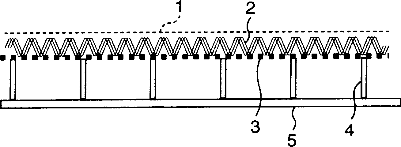
A bipolar zero-gap electrolytic cell comprising an anode comprising an anode substrate constituted of a titanium expanded metal or titanium metal net of 25 to 70% opening ratio, which anode after coating the substrate with a catalyst has a surface of 5 to 50 mum unevenness difference maximum and has a thickness of 0.7 to 2.0 mm. In this electrolytic cell, the possibility of breakage of ion exchange membrane is low, and the anolyte and catholyte have a concentration distribution falling within given range. With this electrolytic cell, stable electrolysis can be performed for a prolonged period of time with less variation of cell internal pressure.

Description

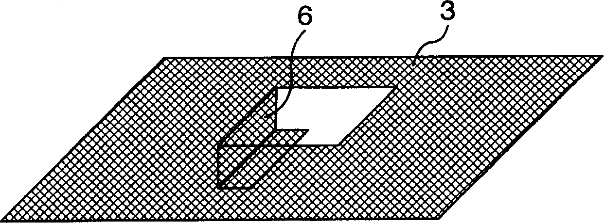
technical field [0001] The invention relates to a bipolar zero-spacing electrolyzer. [0002] This is a bipolar electrolytic cell of a pressure filter type electrolytic cell formed by arranging a plurality of bipolar electrolytic cells through cation exchange membranes. Composition, wherein there are at least two layers in the above-mentioned cathode chamber: a conductive cushion (cushion mat) layer and a cathode layer for hydrogen generation, the cathode layer for hydrogen generation is located on the conductive cushion layer and overlaps with the part in contact with the cation exchange membrane. [0003] This electrolytic cell is characterized in that: the material constituting the anode is titanium expanded metal or titanium wire mesh (gold mesh) with an opening ratio of 25% to 70%, and the catalyst is applied to the above material. , the maximum unevenness of the anode surface is 5μm-50μm, and the thickness is 0.7mm-2.0mm. Background technique [0004] Various proposa...

Claims


Application Information

Patent Timeline
Patent Type & Authority Applications(China)
IPC IPC(8): C25B11/03C25B9/00C25B9/20
CPCC25B11/03C25B9/206C25B9/77C25B11/052C25B9/19C25B1/46
Inventor 宝田博良野秋康秀
Owner ASAHI KASEI KK
Learn More