Eureka AIR delivers breakthrough ideas for toughest innovation challenges, trusted by R&D personnel around the world.

Float arm assembly and method of manufacture

A technology of float arms and floats, which is applied to household components, buoy liquid level indicators, substructures, etc., can solve the problems of increasing weight, affecting performance, increasing costs, etc., and achieve the effects of improving production efficiency, reducing differences, and improving accuracy

Inactive Publication Date: 2006-01-04
WALBRO ENGINE MANAGEMENT
View PDF0 Cites 0 Cited by
  • Summary
  • Abstract
  • Description
  • Claims
  • Application Information

AI Technical Summary

Problems solved by technology

Additionally, the fasteners used in securing the float to the float arm add additional weight to the assembly
thereby affecting the buoyancy of the float in the fuel and thus its performance
Furthermore, the secondary operation of using fasteners to fasten the float into the float arm complicates the assembly process and, therefore, increases the costs associated with the assembly of the float arm assembly

Method used


Image

  • Float arm assembly and method of manufacture
  • Float arm assembly and method of manufacture
  • Float arm assembly and method of manufacture

Examples


Embodiment Construction

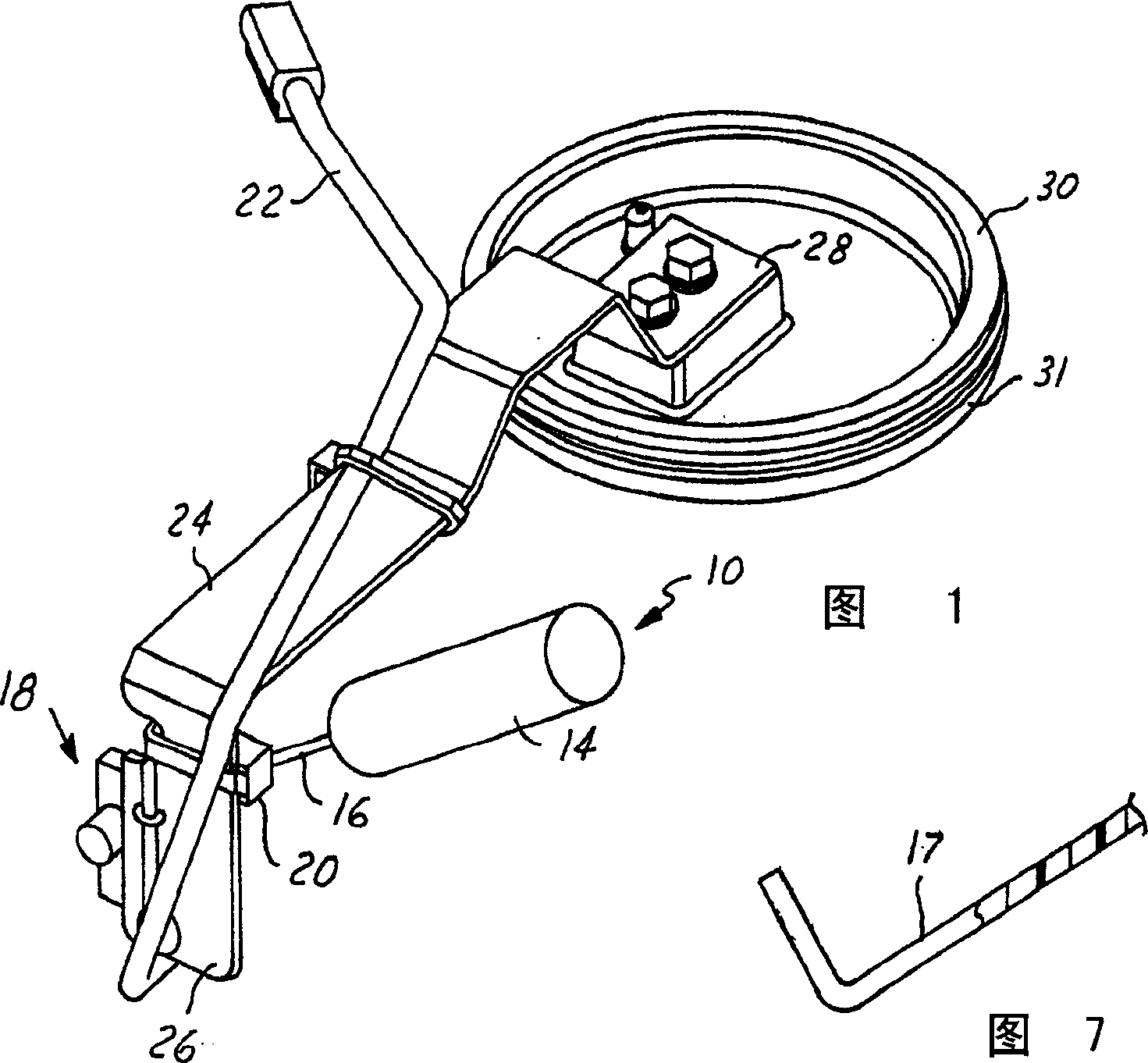
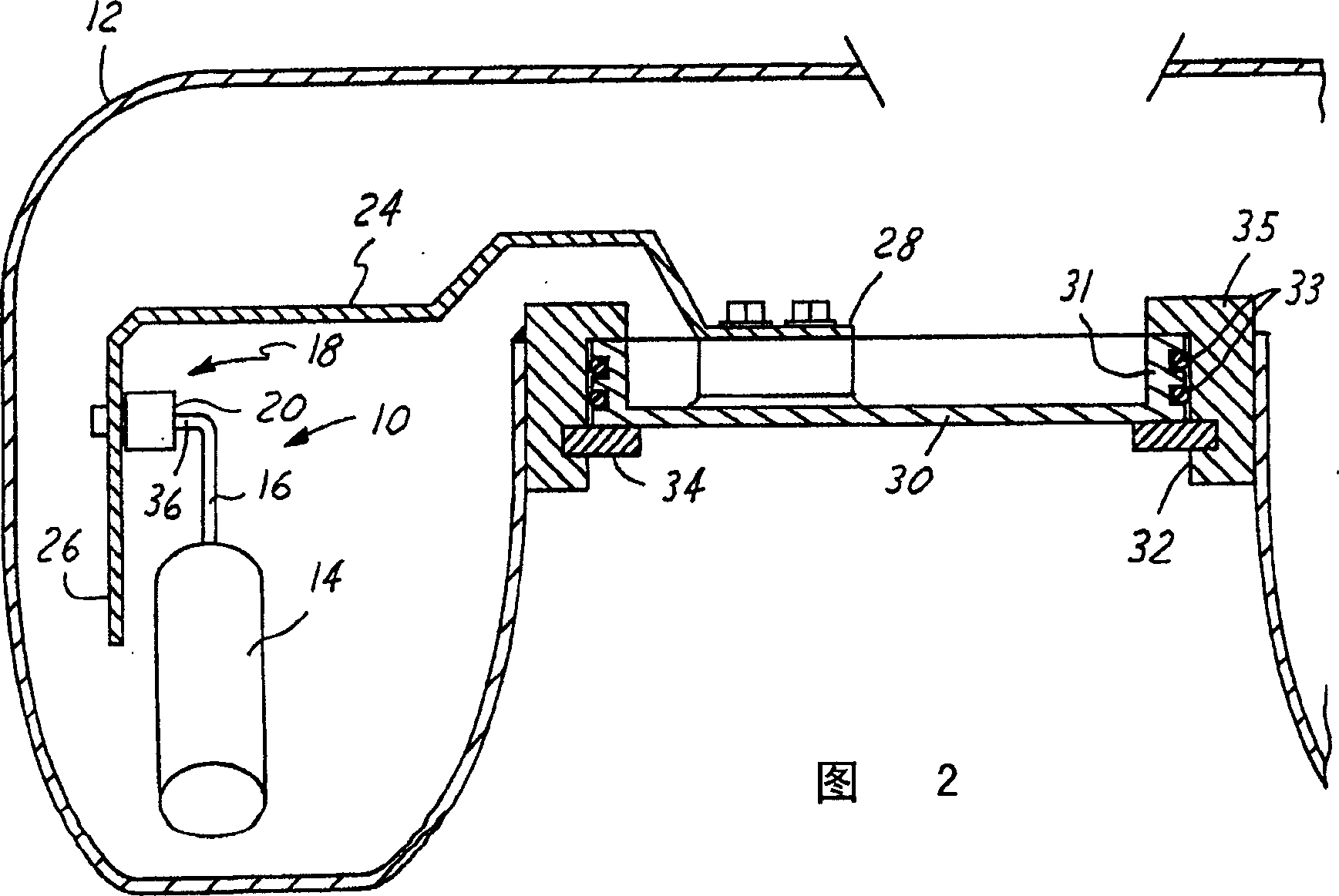
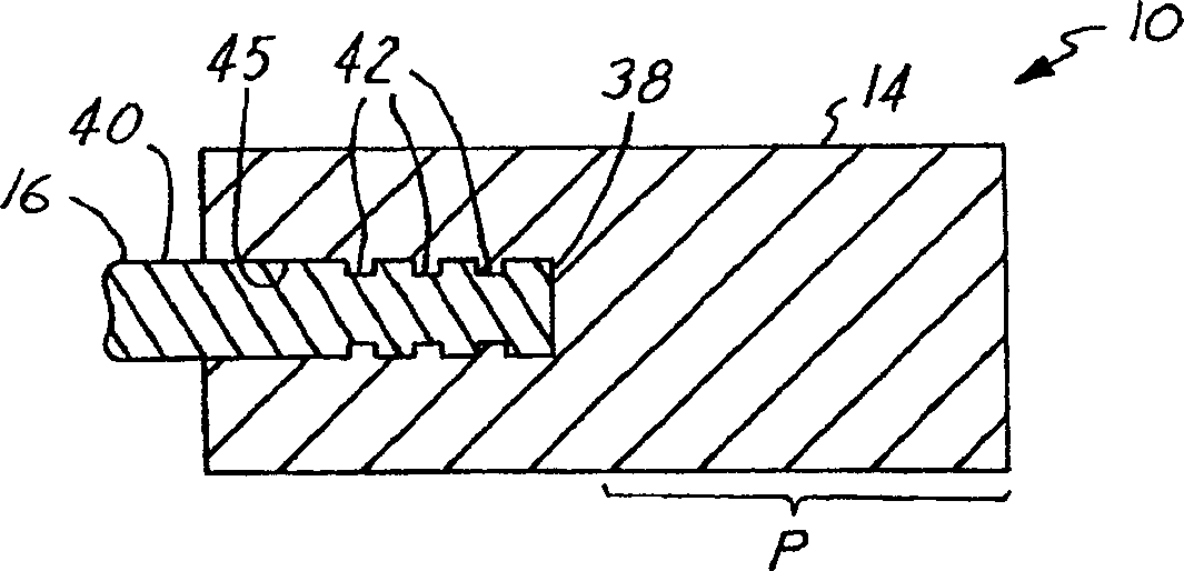
[0016] Referring to Figures 1 and 2 in detail, there is shown a float arm assembly 10 constructed in accordance with one embodiment of the present invention. The float arm assembly 10 is configured for use in a fuel tank 12 (FIG. 2), such as a fuel tank on a motorcycle, RV or vehicle. The assembly 10 has the float 14 molded onto or in at least a portion of the float arm 16 such that the float 14 is carried by the float arm 16 and can be secured to the float arm 16 for removal or lowering between the float 14 and the float arm 16. Slop or jump between float arms 16 . Accordingly, the float arm assembly 10 responds to changes in the fuel position in the fuel tank 12 when there is preferably little relative motion between the float and the float arm 16, and preferably there is no relative motion, thereby It is easy to determine the fuel position in the tank with relative accuracy.

[0017] The float arm assembly 10 is generally configured for use as an integral part of an elect...


PUM

PropertyMeasurementUnit
melting pointaaaaaaaaaa

Abstract

A float arm assembly and method of construction therefore has a float arm with a free end and another end arranged for operable communication with a float arm position sensor. A float is molded to the float arm to provide a unitary and rigid float arm assembly.

Description

technical field [0001] The present invention relates generally to fuel systems, and more particularly to fuel level transmitters for use in fuel tanks. Background technique [0002] Vehicles with internal combustion engines typically have fuel tanks that hold fluid fuel. Typically, the fuel tank has a fuel level transmitter to provide an indication to the user, for example on a fuel level gauge, as to the amount of fuel in the tank. Typically, the fuel level transmitter is coupled to a float arm assembly having a float arm extending through a float to facilitate attachment of the float to the float arm. In addition, it is known to use at least one or more washers combined with fasteners such as self-locking Tinnerman® type washers or nuts and received at adjacent opposite ends of the float, thereby Hold the float securely on the float arm. [0003] Fasteners are used to secure the float to the float arm, typically in secondary operations, resulting in variation between fl...

Claims


Application Information

Patent Timeline
Patent Type & Authority Applications(China)
IPC IPC(8): G01F23/20G01F23/32B60K15/03B29C39/10B29C45/14B29C45/16B29C49/20G01F23/36G01F23/76
CPCG01F23/36G01F23/76B29L2031/7172B29C45/1657B29C45/14311
Inventor K·J·科顿D·H·卡利奥R·J·帕洛特二世
Owner WALBRO ENGINE MANAGEMENT
Why Eureka
Eureka Blog
Learn More