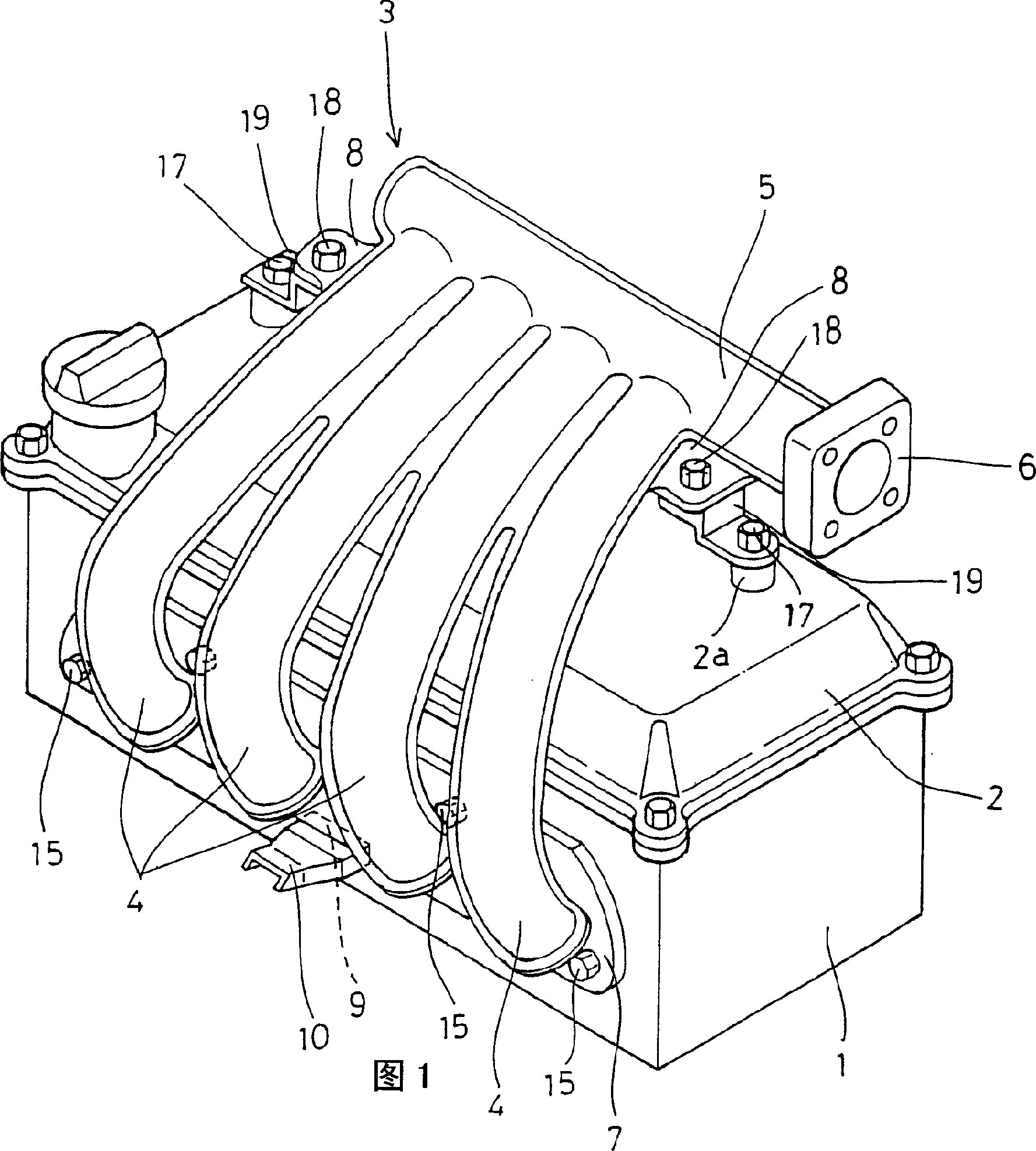
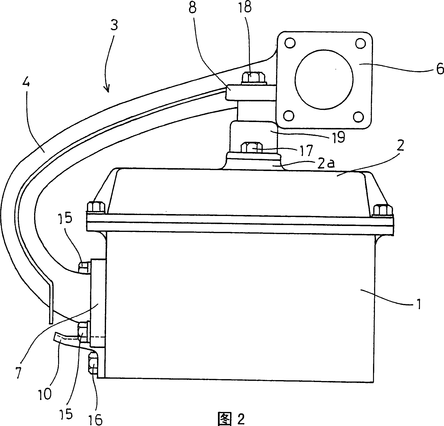
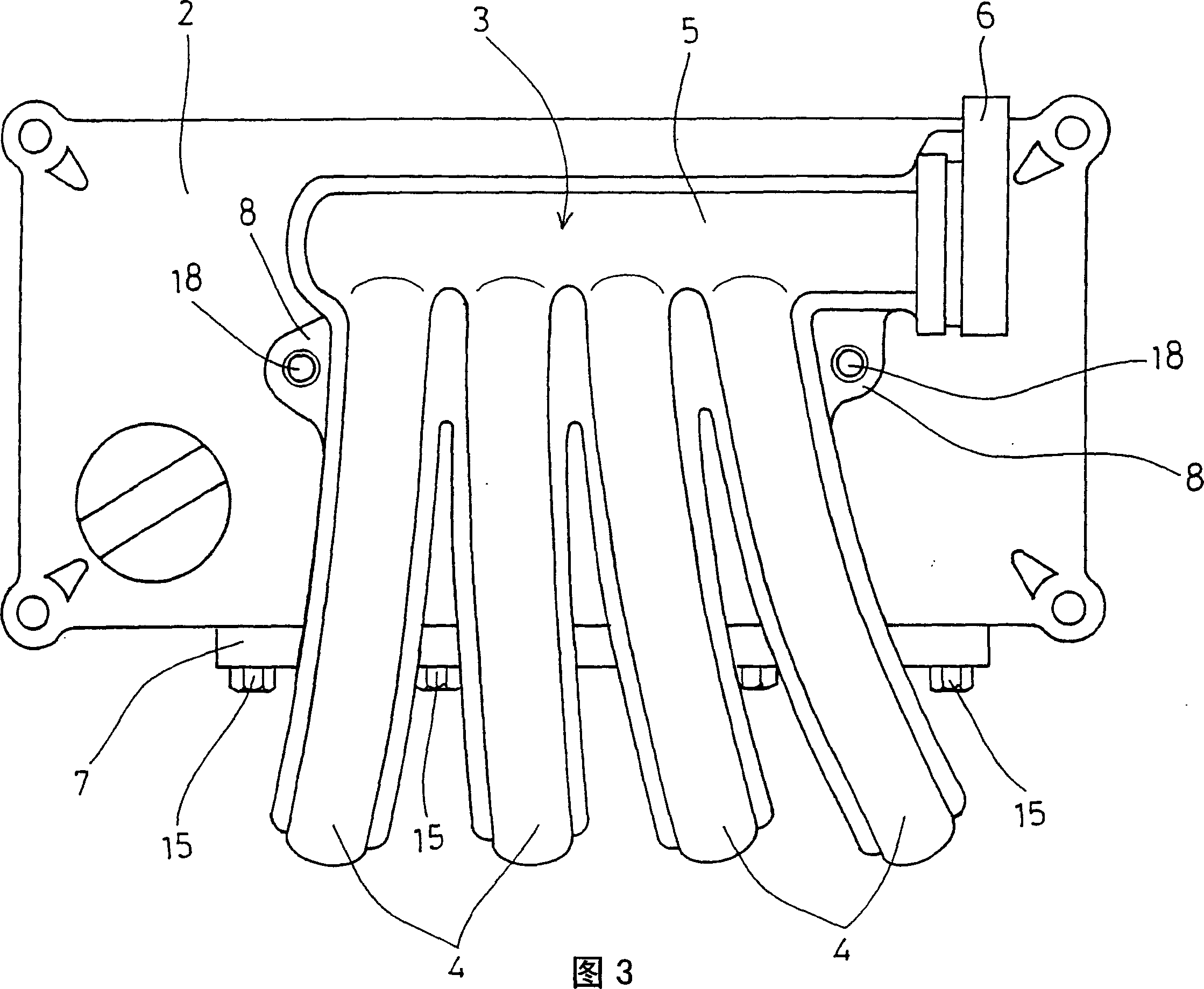
Installation structure of intake manifold
A technology of installation structure and air inlet, which is applied in the direction of fuel air inlet, charging system, combustion air/combustion-air treatment, etc. It can solve the problems of complex structure and achieve the effect of reducing the number of parts
- Summary
- Abstract
- Description
- Claims
- Application Information
AI Technical Summary
Problems solved by technology
Method used
Image
Examples
Embodiment Construction
[0045] Embodiments of the present invention are described below with reference to the drawings.
[0046] FIG. 1 is a perspective view of an installation structure of an intake manifold installed on a cylinder head, FIG. 2 is a side view, and FIG. 3 is a plan view of FIG. 1 .
[0047] In the figure, the top surface of the cylinder head 1 is covered with a rocker cover 2 , and the intake manifold 3 is mounted on the side of the cylinder head 1 through a flange 7 .
[0048] The intake manifold 3 includes four branch pipes 4 having upstream-side ends to which flanges 7 are attached. At the upstream side ends of the four branch pipes 4, a booster chamber portion 5 is provided. The booster chamber portion 5 has a right end to which a throttle chamber mounting flange 6 is attached.
[0049]In this embodiment of the intake manifold 3 , the left and right outer branch pipes 4 , 4 on the sides of the booster chamber 5 are respectively integrally formed with planar portions 8 , 8 protru...
PUM
 Abstract
Description
Claims
Application Information
 - R&D Engineer
- R&D Manager
- IP Professional
- Industry Leading Data Capabilities
- Powerful AI technology
- Patent DNA Extraction
Browse by: Latest US Patents, China's latest patents, Technical Efficacy Thesaurus, Application Domain, Technology Topic, Popular Technical Reports.
© 2024 PatSnap. All rights reserved.Legal|Privacy policy|Modern Slavery Act Transparency Statement|Sitemap|About US| Contact US: help@patsnap.com


