
Circuit breaker and terminal cover

A terminal cover and circuit breaker technology, applied in circuit breaker parts, circuit breaker contacts, switch terminals/connections, etc., can solve problems such as difficulty and difficulty in disassembling the terminal cover

Active Publication Date: 2005-11-23
FUJI ELECTRIC FA COMPONENTS & SYST CO LTD
View PDF1 Cites 8 Cited by
  • Summary
  • Abstract
  • Description
  • Claims
  • Application Information

AI Technical Summary

Problems solved by technology

However, when dismounting this terminal cover, difficult work is unavoidable, in which a tool such as a flathead screwdriver is inserted from the side into the gap between the overlapping main body cover and terminal cover to make it Board open terminal shield while bending
Therefore, it is difficult for the user to remove the terminal cover in the case where a plurality of circuit breakers are mounted in a row on a panel such as a switchboard.

Method used


Image

  • Circuit breaker and terminal cover
  • Circuit breaker and terminal cover
  • Circuit breaker and terminal cover

Examples


Embodiment 1

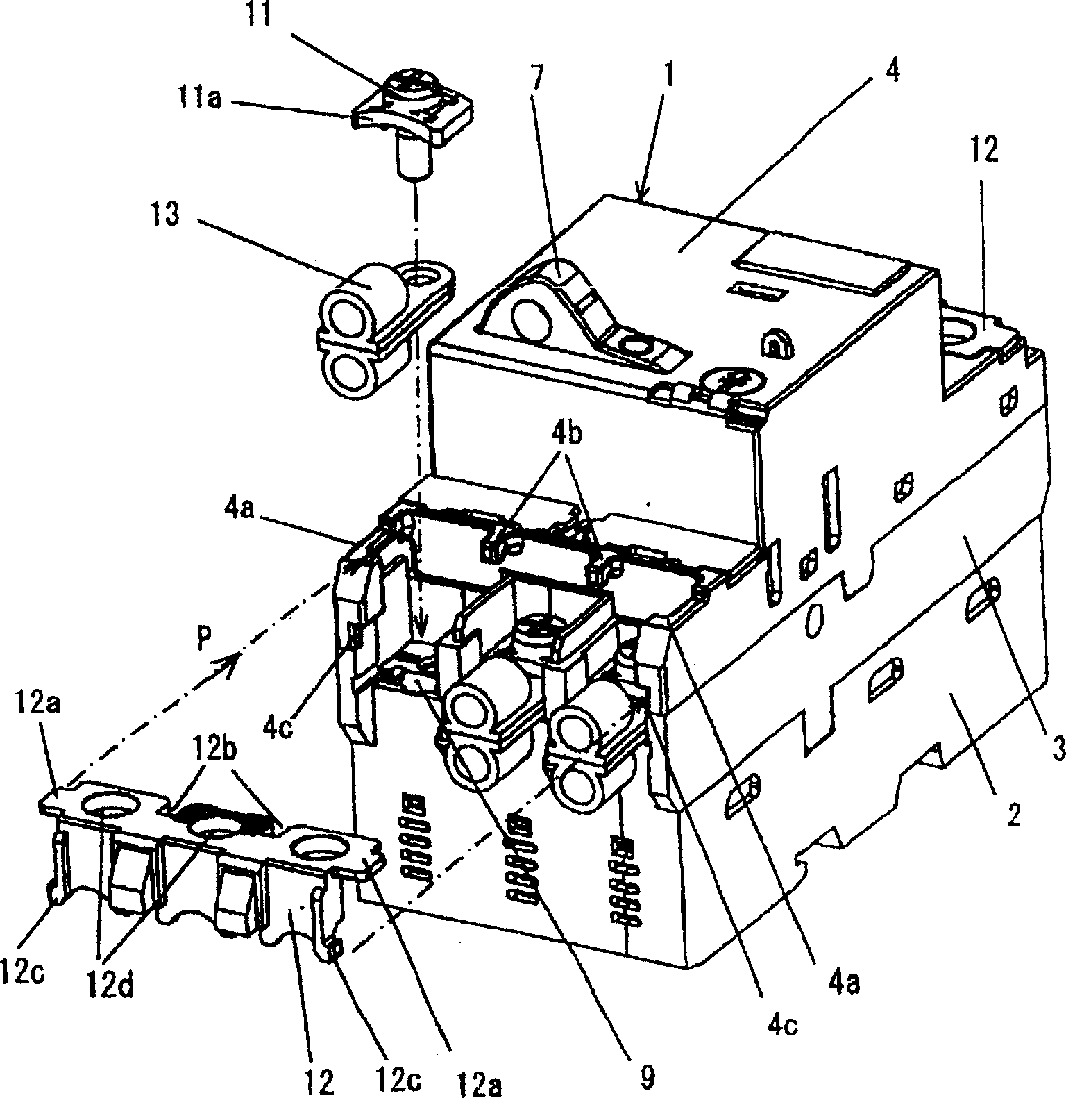
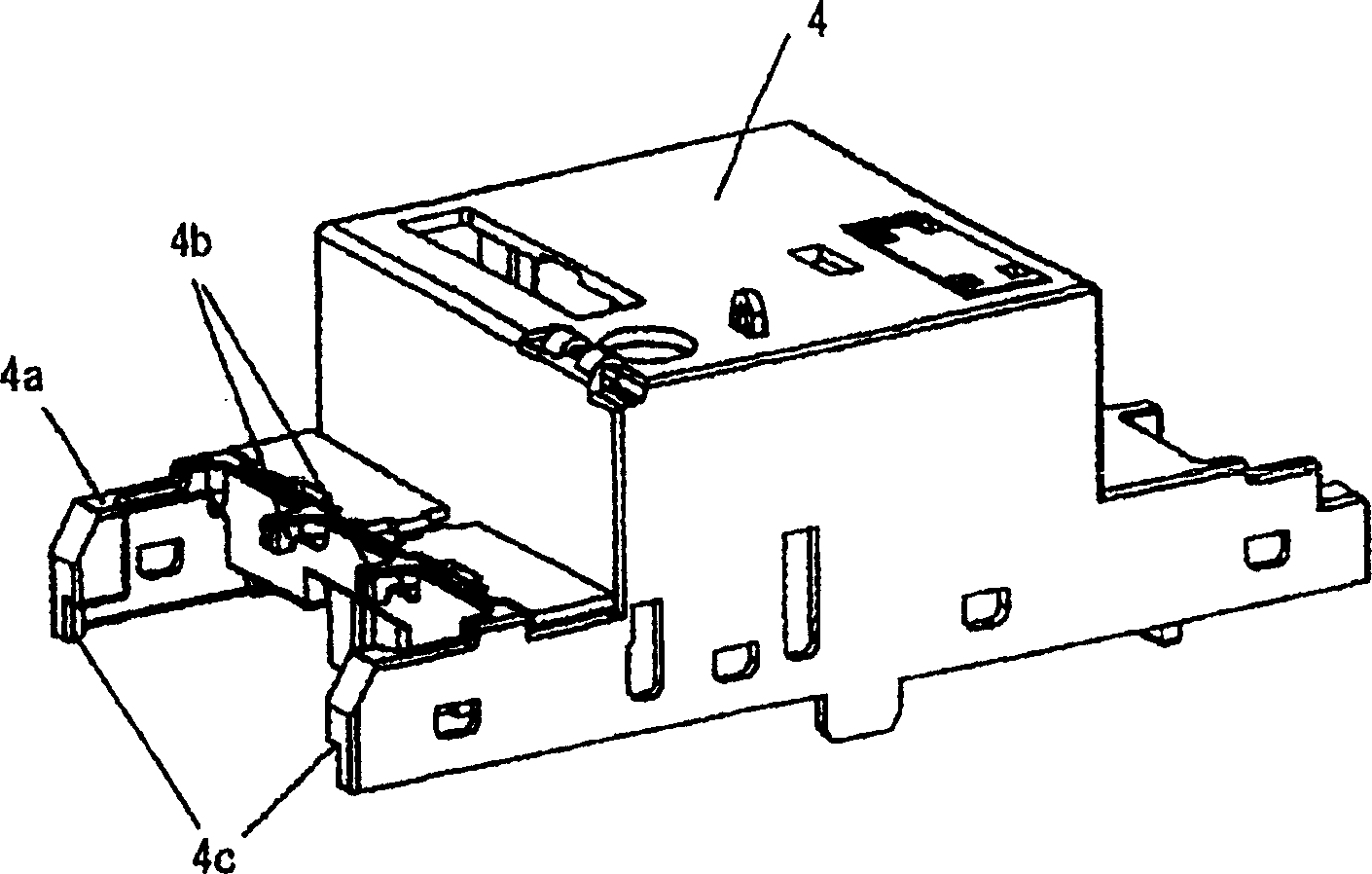
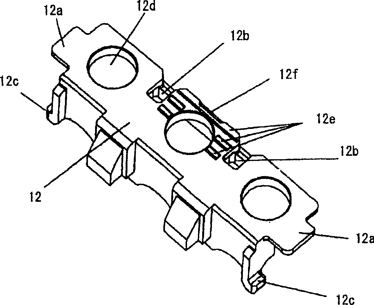
[0024] Figure 1 to Figure 5 Examples are given corresponding to the first to sixth aspects of the present invention. First, in Figure 4A and 4B The overall structure of the circuit breaker is given in, figure 1 The main body case 1 shown in is a molded resin case having a three-part structure consisting of a lower case 2 , an intermediate case 3 and a cover 4 . In the main body casing 1 are incorporated basic components such as a current breaking unit 5 , a switch mechanism 6 , a switch operating handle 7 and an overcurrent tripping device 8 . In addition, on one end and the other end of the main body case 1, the power supply side terminal 9 and the load side terminal 10 of the main circuit are respectively taken out, and on each terminal, a terminal screw 11 is screwed together with a washer 11a to form an external wiring of the terminal section. In addition, the terminal cover 12 formed to cover the front and top of the terminal part according to the present invention...

Embodiment 2

[0030] Next, refer to Figure 6 The elongated terminal cover corresponding to the seventh and eighth aspects of the present invention will be described.

[0031] exist figure 1 In the shown embodiment 1, although the terminal cover 12 covers the upper part and the front part of the terminal screw 11 when it is at the position connected with the main body case 1, the solderless terminal 13 connected to the terminal screw 11 is The cable clamp part protrudes from the front and is not covered and exposed. Thus, the solderless terminal provided as the bare solderless terminal 13 without insulation may be directly touched by hand, which may cause an electric shock. In addition, when the solderless terminals 13 drawn forward from the terminal portion are fastened with the direction of pulling out the cable clamp portion deviated to the left or right, the distance between adjacent solderless terminals 13 is reduced. Small, so it is impossible to ensure the necessary insulation dis...


PUM


Abstract

The present invention provided a mounting structure of a terminal cover of a circuit breaker improved so as to be able to attach and detach the terminal cover on a main body case 1 of the circuit breaker with simple operation. On the circuit breaker, terminals with screws at a power source side and a load side are arranged at a front end part and a rear end part of the main body case 1 of the circuit breaker, and the terminal cover 12 is freely detachably mounted on an upper face side of the main body case corresponding to the terminals. The terminal cover 12 is inserted from a front side in a direction of an arrow mark, and locked and fixed at an assembling position by snap-fit-jointing to the main body case on a mounting face 4a of the terminal cover formed on a side wall of the cover 4 of the main body case. As a snap-fit jointing means, a claw-shaped snap-fit-fastener 4b and a stepped engaging part 4c are formed at the cover side of the main body case. A flange 12a to slide on a cover mounting face 4a of the main body case, an engaging groove hole 12b, into which a claw of the fastener 4b is fitted, and an engaging protrusion 12c fitting into the stepped engaging part 4c, are formed on the terminal cover 12. The terminal cover is locked and fixed to a prescribed assembling position by snap-fit jointing the fastener in a process of inserting the terminal cover from the front side end part of the main body case.

Description

technical field [0001] The present invention relates to a terminal cover applied to a circuit breaker. The circuit breaker referred to here adopts such as a molded circuit breaker and a grounding protection circuit breaker as objects, and also relates to a connection structure of the cover. Background technique [0002] In the above circuit breaker, the terminal cover is combined with the terminals (screw terminals) provided on the power supply side at one end and the load side at the other end of the main body case (molded resin case). This prevents live parts from being exposed to the risk of electric shock from accidental contact. Regarding such a terminal cover, the applicant of the present invention has previously proposed a circuit breaker (see JP-A-2003-257299). The structure of this circuit breaker has a terminal cover detachably connected to the cover of the main body shell. This circuit breaker can connect and fix the cable with the ring-shaped solderless terminal...

Claims


Application Information

Patent Timeline
Patent Type & Authority Applications(China)
IPC IPC(8): H01H73/20H01H9/02H01H71/08H01H71/54H01H73/00H01H73/04H01H73/06
CPCH01H73/045H01H9/0264H01H71/54
Inventor 川田久夫久保山胜典永广勇
Owner FUJI ELECTRIC FA COMPONENTS & SYST CO LTD
Learn More