
Balling device

A technology of pelletizing machine and roller, which is applied in the direction of extrusion granulation by die, granulation on endless conveyor belt, etc.

Inactive Publication Date: 2005-11-16
SHANDONG IRON & STEEL CO LTD +1
View PDF0 Cites 2 Cited by
  • Summary
  • Abstract
  • Description
  • Claims
  • Application Information

AI Technical Summary

Problems solved by technology

[0002] In the prior art, the known technology is the existing double-roll pressure pelletizing machine. This pelletizing machine relies on the dies on the two rollers to pelletize. The rollers are the pelletizing molds. High-hardness and high-wear-resistant metal materials are processed and manufactured, which is very suitable and efficient for processing large-diameter spheres, but it is helpless for processing small round balls with a diameter of less than 20 mm. This is the existing technology main problems

Method used


Image

  • Balling device
  • Balling device

Examples


Embodiment Construction

[0009] In order to clearly illustrate the technical features of the solution, the solution will be described below through a specific implementation mode combined with the accompanying drawings.

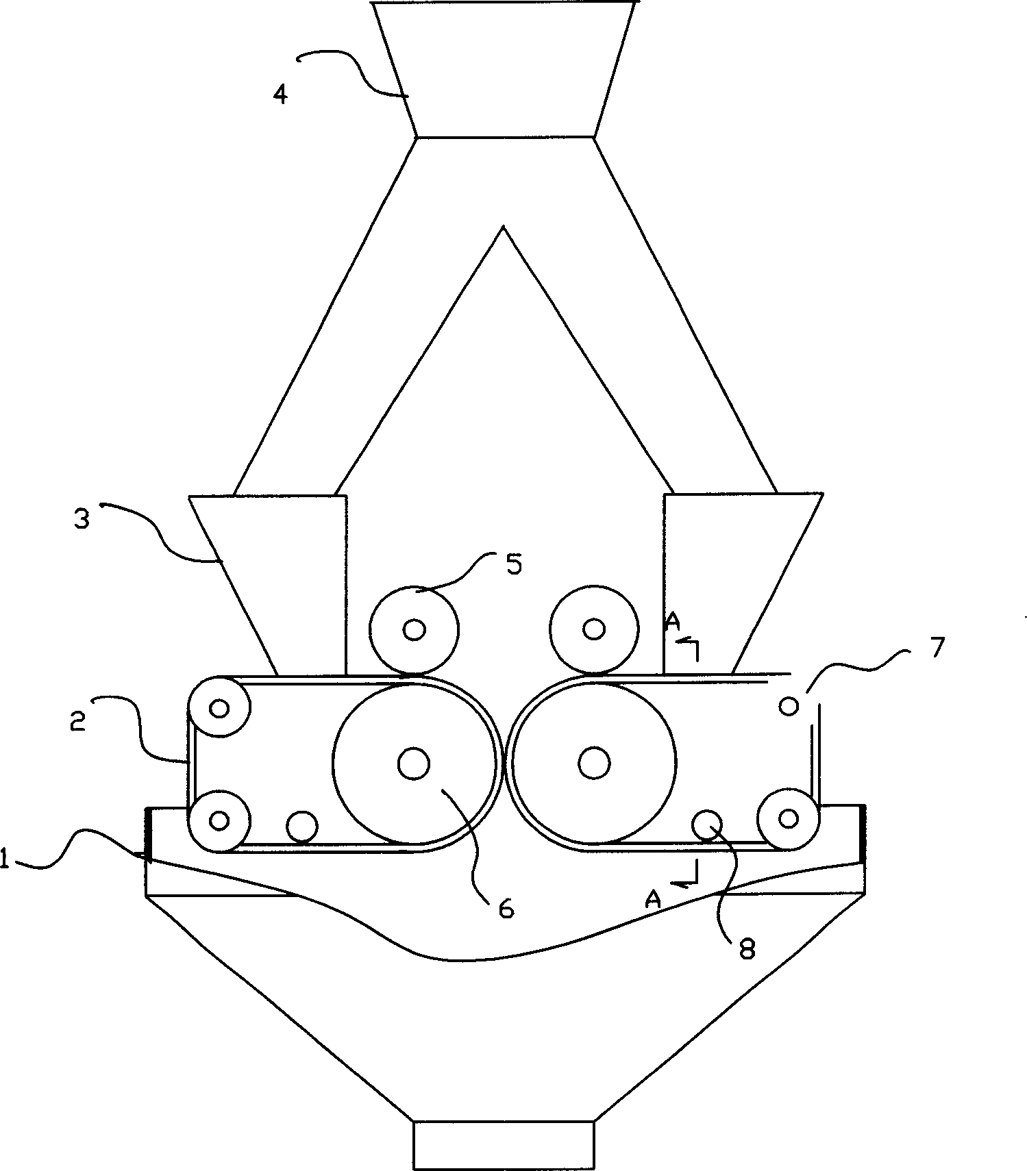
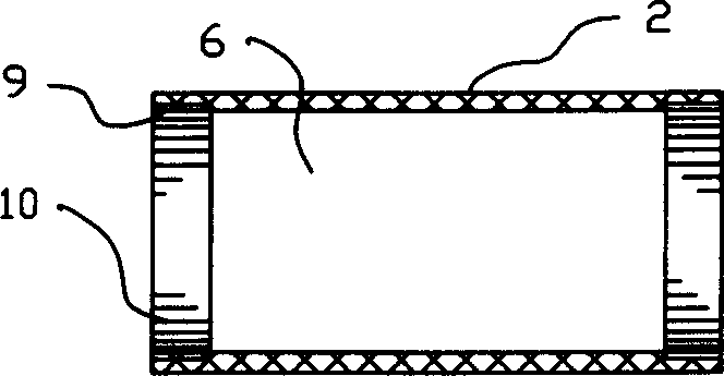
[0010] As can be seen from the accompanying drawings, the pelletizing machine of this program includes a feed bin (4) for supplying pellet powder and a cloth bin (3) for cloth, as well as a motor, A pair of rolls (6) driven by a speed reducer have a discharge chute (1) below the rolls (6). In this solution, there are elastic flexible templates (2) on the outer surfaces of the two rolls (6), and corresponding hemispherical dies are respectively arranged on the opposite faces of the two templates (2). The flexible template (2) is a strip template (2) wound on the roll (6) and the guide roll (7), and supported by the roll (6) and at least one guide roll (7). The specific embodiment adopted is supported by two belt guide rollers (7). There is also a nip roller (5) inside the two cloth ...


PUM


Abstract

A pelletizer is composed of feeding cabin, distributing cabin, a pair of rollers driven by motor and speed reducer, and discharging collector.It features that two band-shaped elastic flexible die plates are used for two rollers and supported by said roller and at least one guide roller. Each die plate has a pressing roller and a vibrator.

Description

Technical field: [0001] The invention relates to mechanical equipment for extruding various powder materials into balls, in particular to a ball making machine. Background technique: [0002] In the prior art, the known technology is the existing double-roll pressure pelletizing machine. This pelletizing machine relies on the dies on the two rollers to pelletize. The rollers are the pelletizing molds. High-hardness and high-wear-resistant metal materials are processed and manufactured, which is very suitable and efficient for processing large-diameter spheres, but it is helpless for processing small round balls with a diameter of less than 20 mm. This is the existing technology The main problems that exist. Invention content: [0003] The present invention aims at the deficiencies in the prior art, and provides a technical proposal for a pelletizing machine. In this proposal, elastic flexible templates are installed on the outer surfaces of the two rolls, and the pelletiz...

Claims


Application Information

Patent Timeline
IPC IPC(8): B01J2/22
Inventor 杨宪礼孟春光卫国强蔡漳平于海波
Owner SHANDONG IRON & STEEL CO LTD
Learn More