
Direct conversion receiver

A technology of receiving signals and local oscillators, which is applied in the directions of multi-frequency modulation conversion, amplitude modulation oscillation demodulation, multi-carrier systems, etc., and can solve problems such as leakage and secondary distortion of mixers

Inactive Publication Date: 2005-11-02
TELEFON AB LM ERICSSON (PUBL)
View PDF1 Cites 0 Cited by
  • Summary
  • Abstract
  • Description
  • Claims
  • Application Information

AI Technical Summary

Problems solved by technology

A problem with traditional direct conversion receivers is the secondary distortion that occurs in the mixer
Secondary distortion is caused by the fact that mixers are inherently nonlinear devices
Therefore, LO leakage is not suppressed in conventional direct conversion receivers

Method used


Image

  • Direct conversion receiver
  • Direct conversion receiver
  • Direct conversion receiver

Examples


Embodiment Construction

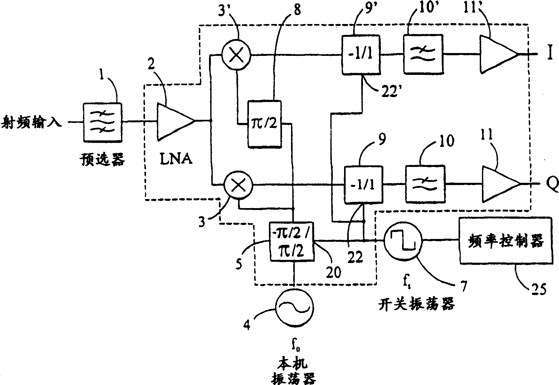
[0017] figure 2 A block diagram showing a preferred embodiment of the invention. A radio frequency signal is received at the RF input and sent to a preselection filter 1 and then to a low noise (LN) amplifier 2 . The input signal is then decomposed and fed to an up-mixer 3 ′ and a down-mixer 3 . The local oscillator 4 generates a sine wave tuned at the same frequency as the carrier of the incoming RF signal. The sine wave generated by the local oscillator 4 is fed to an input of the switchable phase change element 5, and the phase of the input sine wave is changed by -π / 2 or π / 2 radians (-90° or 90°) according to the state of the control input 20 ). Although the phase transitions do not have to be -π / 2 and π / 2, the difference between the first phase change and the second phase change must be equal to π radians (or 180°).

[0018] The switching oscillator 7 generates a switching signal having two states (eg a square wave pulse train) corresponding to an "on" state and an "o...


PUM


Abstract

A homodyne receiver according to the present invention includes a signal input and first and second mixers coupled to the signal input. A local oscillator provides a reference signal at the frequency of modulation of the input signal. The reference signal output by the local oscillator is passed through a switchable phase change element, the output of which is coupled directly to the first mixer and indirectly to the second mixer through a second phase change element. The switchable phase change element changes the phase of an input signal by a predetermined phase based on the state of a control input, such that the output of the phase change element in one state is pi radians out of phase with the output of the phase change element in the other state. The second phase change element changes the phase of an input signal by pi / 2 radians. The outputs of the mixers are coupled to a pair of switchable inverters and low pass filters. Switching of the switchable phase change element and the switchable inverters is controlled by a switching oscillator.

Description

[0001] This application is a divisional application of the patent application whose application number is 99807661.9. technical field [0002] The present invention relates generally to direct conversion receivers (or homodyne receivers) which separate a received signal into in-phase (I) and quadrature (Q) components while also reducing binary noise due to mixer nonlinearities. Sub-intermodulation and feedback on the tuned LO. Background technique [0003] Superheterodyne receivers are the most widely used receivers in modern communication devices. Such receivers are found on televisions, telephones or radios in the home, office or car. The superheterodyne receiver will (the carrier frequency is f 1 of) an input radio frequency (RF) signal with a local oscillator generated (at frequency f 2 ) sinusoidal signals are mixed (or multiplied). The resulting output signal consists of two frequencies shifted centered on the input signal at the sum and difference of the combined ...

Claims


Application Information

Patent Timeline
IPC IPC(8): H03D1/22H03D7/16H04B1/30H04L27/38
CPCH03D1/2245H04B1/30H03D1/22
Inventor D·阿派尔小C·戈雷
Owner TELEFON AB LM ERICSSON (PUBL)
Learn More