Sewing machine with faulty thread mark detection device

A detection device and sewing machine technology, applied in the field of sewing machines, can solve problems such as inaccuracy and unreliability

Inactive Publication Date: 2005-09-07
DURKOPP ADLER AG
View PDF1 Cites 7 Cited by
  • Summary
  • Abstract
  • Description
  • Claims
  • Application Information

AI Technical Summary

Problems solved by technology

This known design is at least very imprecise and unreliable

Method used


Image

  • Sewing machine with faulty thread mark detection device
  • Sewing machine with faulty thread mark detection device
  • Sewing machine with faulty thread mark detection device

Examples


Embodiment Construction

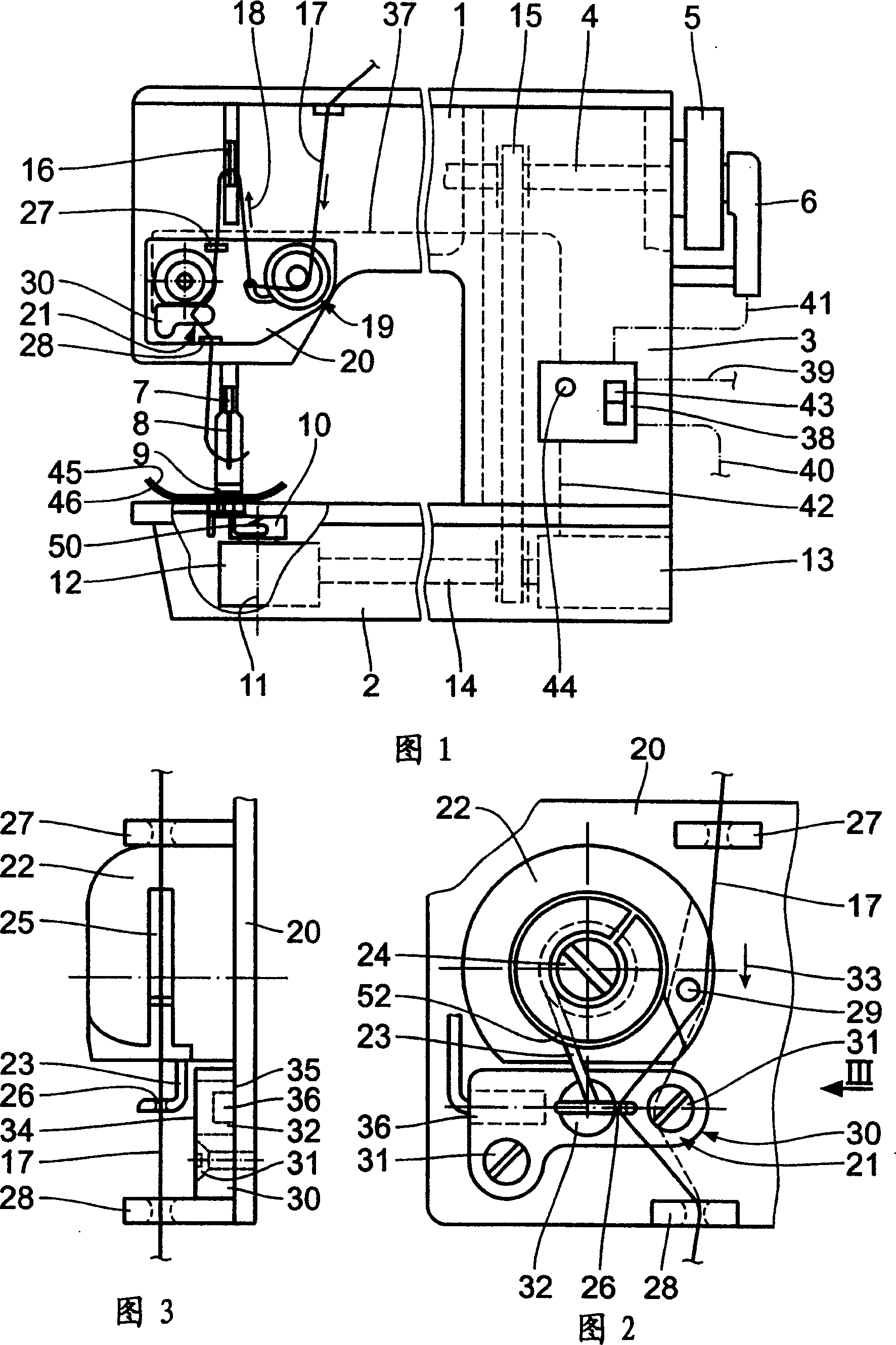
[0014] As shown in FIG. 1, a sewing machine generally includes a top arm 1, a shell-shaped base plate 2, and a column 3 connected to the top arm 1 and the base plate 2 at its two ends, so that the sewing machine becomes a C-shape. An arm shaft 4 is located in the top arm 1, and the end of the arm shaft 4 outside the top arm 1 supports a handwheel 5, and a momentum transmission device 6 is installed on the arm shaft 4 next to the handwheel 5. The actuation of the needle bar 7 with a needle 8 and a presser foot 9 usually comes from the arm shaft 4 .

[0015] A vertical hook / shuttle 10 is located within the base plate 2 for rotation about a vertical axis 11 of the hook support 12 . The wire hook 10 is actuated via a wire hook drive shaft 14 by a drive motor 13 arranged in the base plate 2 below the column 3 . The hook drive shaft 14 also actuates the arm shaft 4 via a belt drive 15 .

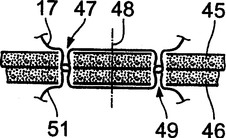
[0016] The top arm 1 also holds a thread take-up lever 16 for a needle thread 17 also driven ...


PUM


Abstract

The sewing machine is provided with a device (21) to detect an incomplete stitch disposed between a thread winding lever (16) and a needle. The incomplete stitch detection device guides the upper thread (17) and substantially crosses the main direction (33) of the upper thread (17) to have a deflective eye (26). The deflection of the eye (26) produces a change of a magnetic field created by a magnet (32). The change of the magnetic field is detected by a sensor (36) and changed to a control signal of the sewing machine.

Description

technical field [0001] The present invention relates to a sewing machine, which comprises: a needle, which can be reciprocated up and down by an arm shaft, and can transmit needle thread to the needle along a needle thread supply direction; a thread hook matched with the needle; a needle thread supply A thread take-up lever positioned upstream of the needle to guide the needle thread; a faulty stitch detection device for generating an electrical signal based on the tension of the needle thread relative to the arm shaft rotation angle; and a A microprocessor for generating a control signal based on the electrical signal and the angle of rotation of the arm shaft. Background technique [0002] US Patent 4170951 discloses a sewing machine with a thread tension detection device between the thread tensioner and the thread take-up lever. The device basically consists of a downwardly open U-shaped deflector holding strain gauges. The needle thread coming from the thread tensioner...

Claims


Application Information

Patent Timeline
IPC IPC(8): D05B51/00
CPCD05B51/00F24C7/02F24C15/008
Inventor J·恩斯S·霍沙加斯A·格拉默
Owner DURKOPP ADLER AG
Why Eureka
Try Eureka